Current Transformer: Star side and Polarity
| Rod Hughes Consulting General Web Site | Applications Home | Innovations and Solutions Home | A bit about Rod Hughes |
|
|---|
Note - if the navigation pane on the left of this window is not visible, click the 2-pane icon on the top bar
Fairly common questions are:
- which side to star the CT?
- which side to have the polarity?
- are there any consequences or implications?
The answer, as always, depends on the application, and then to some extent on the capabilities and settings of the IEDs!
Non-directional Protection
If the protection elements "50" or "51" elements (IEEE C37-2008 are purely non-directional, they only operate on the magnitude of current so at least in that respect, polarity and star are immaterial.
The two independent choices star side and polarity sides is only a question of standardisation in order to be consistent across the various locations simply to ensure there is no confusion for the technicians.
Directional Current, Distance and Power- based Applications
However, if the "50" or "51" elements (IEEE C37-2008) are now directional as "67" devices, or perhaps a distance function "21", reverse/over power function "32", or any other power related function including metering etc, the direction of power flow becomes significant.
If the IED allows changing of the polarity seen by the IED as part of its available settings, the direction can be set to suit the application as part of commissioning.
As most modern directional-based relays have polarity settings. then as with non-directional relays, the polarity of the CT is arguably just a matter for company convention.
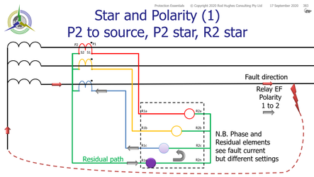
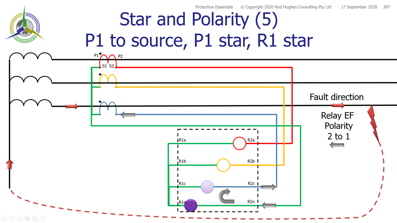
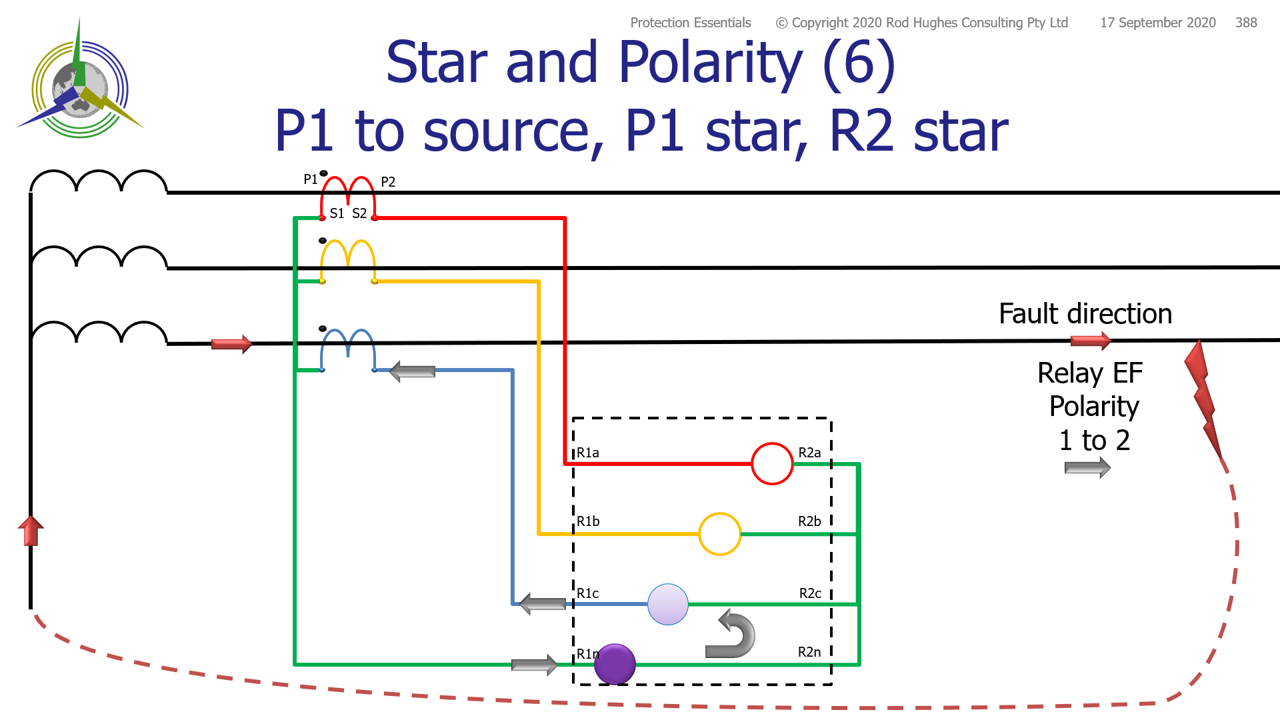
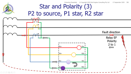
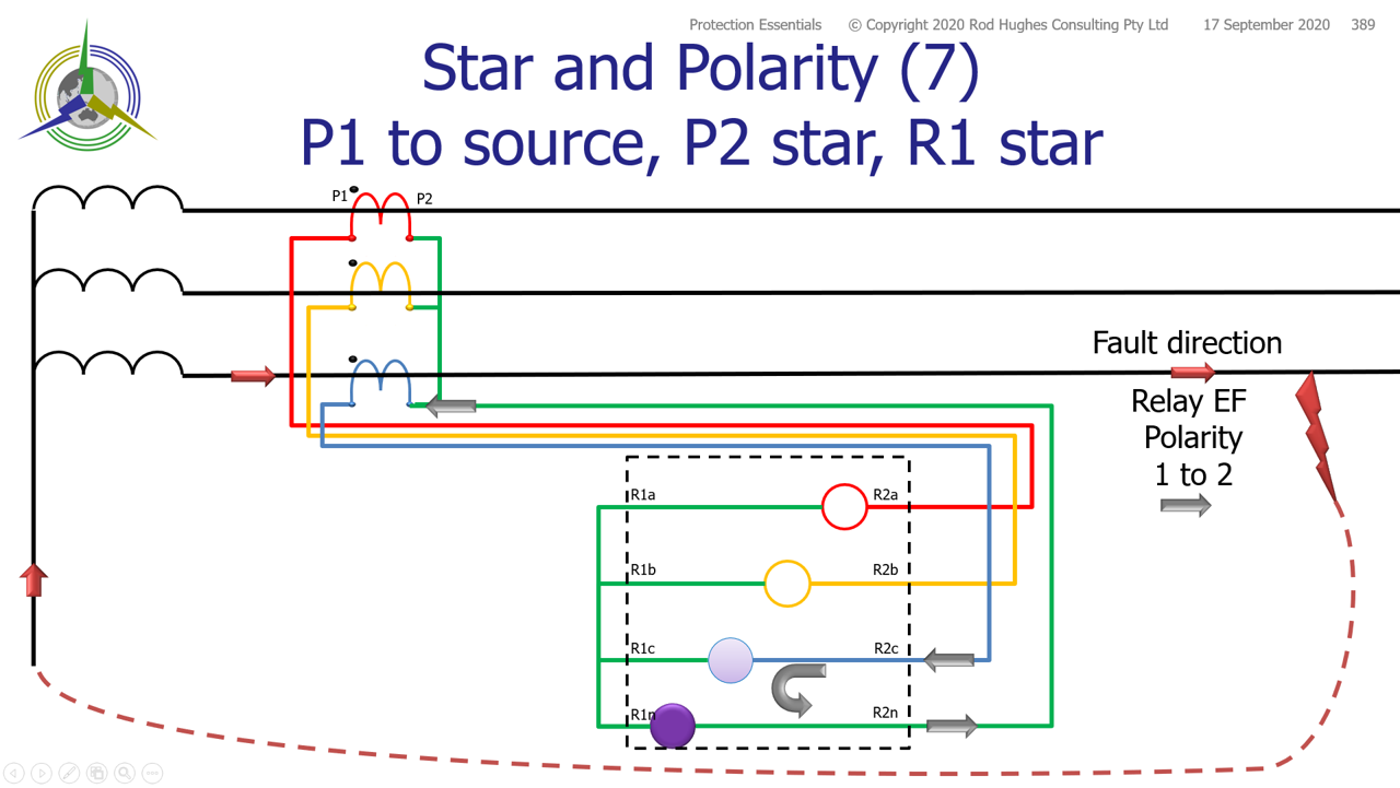
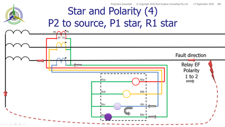
If we consider directional overcurrent and earth fault relays connected to CTs in a Holmgren connection, there are eight possible combinations requiring consideration of the protection element forward/reverse setting.
This can be shown if we consider an earth fault "downstream" of the CT point and the direction of current flow in the relay earth fault element that will cause operation.
P2 towards source | P1 towards source | |
|---|---|---|
| CT Star source side | CT P1 is connected to relay R1 Note direction of current through the relay Phase relay: R2c to R1c Earth Fault relay: R1n to R2n | CT P2 is connected to relay R2 Note direction of current through the relay Phase relay: R1c to R2c Earth Fault relay: R2n to R1n This is opposite #1 as both CT polarity sense as well as relay star has swapped |
CT | CT P1 is connected to relay R2 Note direction of current through the relay Phase relay: R1c to R2c Earth Fault relay: R2n to R1n This is opposite #1 as only relay star side has changed | CT P2 is connected to relay R1 Note direction of current through the relay Phase relay: R2c to R1c Earth Fault relay: R1n to R2n This is opposite #5, but the same as #1 as you can see the wiring arrangement is identical |
CT Star load side | CT P2 is connected to relay R1 Note direction of current through the relay Phase relay: R1c to R2c Earth Fault relay: R2n to R1n This is opposite #1 | CT P1 is connected to relay R2 Note direction of current through the relay Phase relay: R2c to R1c Earth Fault relay: R1n to R2n This is same as #1 |
CT Star load side | CT P2 is connected to relay R2 Note direction of current through the relay Phase relay: R2c to R1c Earth Fault relay: R1n to R2n This is same as #1 | CT P2 is connected to relay R1 Note direction of current through the relay Phase relay: R1c to R2c Earth Fault relay: R2n to R1n This is opposite #1 |
Clearly star side is irrelevant as #1, #4, #6, and #7 are identical,
whilst #2, #3, #5, #8 are identical but opposite the others.
It is critical however to match polarity of CT and relay connections ... noting many relays now allow you to "swap" the polarity sense of the relay by settings.
Differential Applications
This is arguably a little more complicated in the "it depends" consideration
- Merz-Price Circulating Current High Impedance Differential
- Low Impedance Differential
Copy this permanent link to this page: https://rhconsult.tiny.us/yckz4vp3
- Protection Systems Engineering
- IEC 61850 Engineering
I provide a range of courses for company-specific in-house training and occasional public invitation courses. Contact me for details.
Contact Me
A phone call is nearly always welcome depending on the time of night wherever I am in the world.
Based in Adelaide UTC +9:30 hours e.g.
| April-September | Noon UK = 2030 Adelaide |
| October-March: | Noon UK = 2230 Adelaide |
Mobile + 61 419 845 253
Extra Notes:
No Waiver, No Licence:
Rod Hughes Consulting Pty Ltd accepts no direct nor consequential liability in any manner whatsoever to any party whosoever who may rely on or reference the information contained in these pages. Information contained in these pages is provided as general reference only without any specific relevance to any particular intended or actual reference to or use of this information. Any person or organisation making reference to or use of this information is at their sole responsibility under their own skill and judgement.
This page is protected by Copyright ©
Beyond referring to the web link of the material and whilst the information herein is accessible "via the web", Rod Hughes Consulting Pty Ltd grants no waiver of Copyright nor grants any licence to any extent to any party in relation to this information for use, copy, storing or redistribution of this material in any form in whole or in part without written consent of Rod Hughes Consulting Pty Ltd.
