Transformer Differential and Restricted Earth Fault
- Rodney Hughes
| Rod Hughes Consulting General Web Site | Applications Home | Innovations and Solutions Home | A bit about Rod Hughes |
|
|---|
Note - if the navigation pane on the left of this window is not visible, click the 2-pane icon on the top bar
Differential protection in principle is straight forward - what goes in, should come out!
If there is a difference there is a fault.
The IEEE C37.2 reference number for this is 87.
IEC 61850 uses the PDIFF Logical Node.
This can be applied to a busbar, a generator or motor winding, transformer or to a power line. Due to the distances involved, line differential requires special techniques (not discussed here) to compare the current at each end .
Using CTs to measure the current at each end of the unit of power system we wish to protect - and hence differential is referred to as unit protection - we can now compare these currents.
In the case of any winding differential scheme - i.e. associated with a generator winding, motor winding or transformer winding the differential scheme may be a specific arrangement known as Restricted Earth Fault (REF) which only detects earth fault within the CT zone - phase to phase faults are not detected.
Modern times have seen a move to microprocessor based relays where individual CT cores at each end are connected directly to individual inputs on the relay. The relay then uses numerical techniques to sum the currents as required.
However the principles of differential protection were borne in the application of the so called circulating current Merz-Price connection. This allows us to use the CT connections to circulate any through current around the CTs as shown on this page: High Impedance, Merz-Price, Circulating Current Differential.
In the case of transformers with the Merz-Price arrangement, things are more complicated because the currents on the HV side of the transformer may be different to the currents on the LV side so simple comparison is not possible - care must be taken to connect the CTs in the right arrangement to cater for not only ratio differences but also transformer vector shifts.
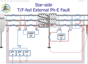
- In the case of REF schemes we must connect the CTs in parallel to each other and the relay.
- In the case of the overall transformer differential, the vector correction means that the delta side CTs are connected in star, whilst the star side CTs are connected in delta.
Due to these mutually exclusive CT connection arrangements it is not possible to directly connect the REF relay and overall differential relay to the same CT cores.
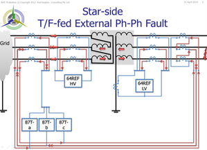
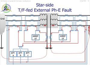
The following diagrams (click to enlarge) show the current flows associated with a phase-to-earth and phase-to-phase fault fault on the star side.
If there is only a single set of CTs available, it is therefore necessary to use an Interposing CT (not shown) to "split" the current from the single CT cores to be able to be connected in the right arrangements. Examples of this interposing CT arrangement is given in the Alstom "Network Protection Application Guide" book, Figure 16.13 and 16.14 of the May 2011 Edition.
Even in star-star transformers we cannot use a single set of CTs on each side.
As we can see the REF schemes on each side have all the CTs directly connected on their S1 and S2 terminals.
The overall differential cores however are connected phase-by-phase.
If the REF and the TF diff relays are connected to the same set of CT cores, the following individual situations occur:
- the TF diff will loose its phase discrimination since all the S1 of all six CTs are are joined together.
- The REF elements will lose their HV - LV discrimination, again because all S1 terminals are joined together and both elements are in parallel.
- There would now be five relay elements all connected in parallel to the six CT cores connected in parallel. Hence the internal fault current will split down each of the relay elements according to their respective impedances. Hence there would be a severe reduction in sensitivity, although of course these elements generally have low settings of say 10% of rated current compared to maximum fault currents of 20 x rated. This problem can be reduced if the individual phase elements and on eof the REF elements are discarded (they are all in parallel anyway) but then it is just one element with no discrimination of the fault location which was the original reason for having the TF diff and separate REF on each winding.
Copy this permanent link to this page https://rhconsult.tiny.us/bdfbrjeh
Contact Me
A phone call is nearly always welcome depending on the time of night wherever I am in the world.
Based in Adelaide UTC +9:30 hours e.g.
| April-September | Noon UK = 2030 Adelaide |
| October-March: | Noon UK = 2230 Adelaide |
Mobile + 61 419 845 253
Extra Notes:
No Waiver, No Licence:
Rod Hughes Consulting Pty Ltd accepts no direct nor consequential liability in any manner whatsoever to any party whosoever who may rely on or reference the information contained in these pages. Information contained in these pages is provided as general reference only without any specific relevance to any particular intended or actual reference to or use of this information. Any person or organisation making reference to or use of this information is at their sole responsibility under their own skill and judgement.
This page is protected by Copyright ©
Beyond referring to the web link of the material and whilst the information herein is accessible "via the web", Rod Hughes Consulting Pty Ltd grants no waiver of Copyright nor grants any licence to any extent to any party in relation to this information for use, copy, storing or redistribution of this material in any form in whole or in part without written consent of Rod Hughes Consulting Pty Ltd.