Transformer Differential and REF CT Configurations
- Rodney Hughes
| Rod Hughes Consulting General Web Site | Applications Home | Innovations and Solutions Home | A bit about Rod Hughes |
|
|---|
Note - if the navigation pane on the left of this window is not visible, click the 2-pane icon on the top bar
In the "good old days" Transformer Differential protection and Winding Restricted Earth fault protection "had" to use individual CT cores as shown below due to the necessity of delta CTs on the star side of the transformer and the need to minimise total loop impedance to keep CT kneepoint requirements as low as possible.
The example uses a single phase-to-earth external fault on the star side of the transformer to show stability of the protection functions.
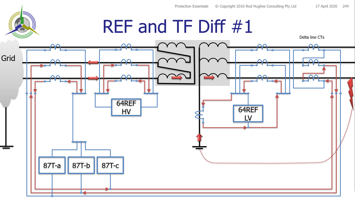
Clearly this is an expensive solution in regards to CT cores and of course installation and testing.
Unfortunately with delta connected line CTs on the star side of the transformer, there are not many options other than segregated REF and TF Diff CTs on the star side of the transformer. Of course not to forget that it was always a nuisance at the equipment procurement stage to remember to order one set of line CTs for the star side with a different CT ratio i.e. "xxxx/1 A" for the REF and "xxxx/0.577 A" for the TF Diff delta line CTs ... invariably the TF vendors would just provide CTs with expected star connection and then you have a problem of mismatched currents on the secondary of the CTs
However with the advent of electronic, in particular numerical relays, alternative arrangements have become possible, based on using star line CTs on the star side of the transformer ... i.e. "xxx/1 A" line CTs.
The use of a special interposing CT, the star connection line CTs can be converted to match the necessary current paths from the transformer delta side CTs.
These interposing CTs must be carefully chosen so as not introduce their own saturation effects onto the secondary current waveforms!
In numerical relays, the function of the interposing CT can be replaced as an internal setting of the TF Differential relay which does the conversion "numerically" inside the relay.
This leads to an arrangement as below:
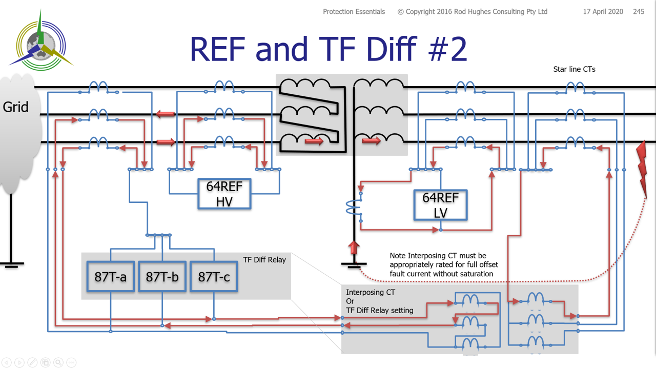
However this still shows the expensive four sets of line CTs.
Since the system is now using star line CTs, the system can be simplified as shown below.
BUT ... there is an inevitable "but" in any simplification ...
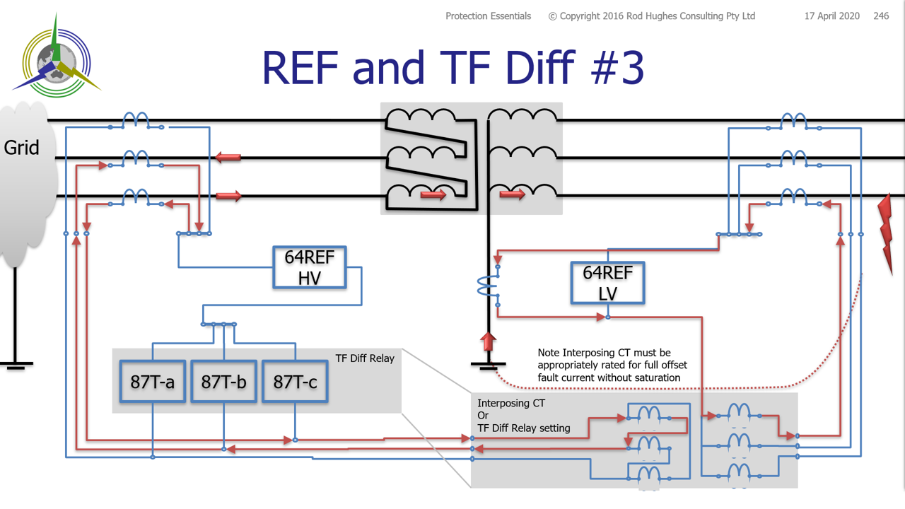
The "BUT" is in relation to CT sizing and setting of the REF operating voltage.
When there was four sets of CTs, the CT requirements for each function of REF and TF Diff were totally independent.
By combining the functions onto a common set of line CTs, the loop burdens are SIGNIFICANTLY changed.
Just considering the star side of the transformer (although same philosophy applies to the delta side), combing REF and TF Diff onto the same CTs, this will need specific engineering considerations ... you need to satisfy two application requirements for CT sizing .. and since many don't understand what they are doing with just one type of CT requirement, it is really going to cause problems and mis-application causing things to operate when they shouldn't or not operate when they should.
Similarly the REF relay has both a setting and kneepoint calculation both with Rloop ... but now it is not just simply the traditional Ohm's Law based formula assuming the relay is mid point between the neutral CT and the line CTs:
The REF relay has both a setting and kneepoint calculation both with Rloop ... but now it is not just simply assuming the impedance on the neutral-connection side of the relay is the same as the line-connection side of the relay which therefore gives an equation of:
Vk >=K x If x 2 x (Rct + Rloop)
the "2" is "sacrosanct"according to application of Ohm,'s Law!
"K" is a vendor-specific factor for transient conditions.
The low impedance TF diff application will also have certain vendor-specific CT requirements with an Rloop component
Because Rloop is not "equal" on either side of the relay, applying Ohm's Law around the loop you get:
- the line CT impedance: RlineCT
- wire impedance from the line CT to the TF Diff relay: RlineCT_to_TFdiff , and
- the TF diff relay impedance: RTFdiff , and
- wire impedance from the TF Diff relay to the REF relay: RTFdiff_to_REF , and
- wire impedance from the REF relay to the neutral CT: RREF_to_Rneut , and
- the neutral CT impedance: RneutCT, and
- wire impedance from the the neutral CT back to the REF: RneutCT_to_REF, and
- wire impedance from the REF back to the line CT: RneutCT_to_lineCT
Hence Vk >= K x If x (RlineCT + Rlinect_to_TFdiff + RTFdiff + RTFdiff_to_REF + RREF_to_RneutCT + RneutCT + RneutCT_to_REF + RneutCT_to_lineCT)
As the REF relay is also not "equi-distant" from the CTs and hence you need to satisfy the worst case setting requirements of a minimum REF setting voltage with one CT saturated of :
Vs1 >= K x If x (RREF_to_lineCT + RlineCT + Rlinect_to_TFdiff + RTFdiff + RTFdiff_to_REF)
Vs2 >= K x If x (RREF_to_neutCT + RneutCT + RneutCT_to_REF)
So please be careful especially when converting old transformer protection schemes with four sets of line CTs to use just two sets and a numerical relay!
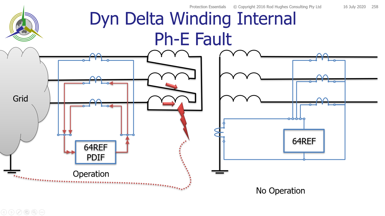
REF for Delta windings
delta windings are not in themselves sources of Zero Sequence current - the delta is a zero-sequence-trap.
However a delta winding may itself be subject to a winding-to-earth fault and hence REF protection is still useful
Permanent link to this page: https://rhconsult.tiny.us/4cxs9447
- Protection Systems Engineering
- IEC 61850 Engineering
I provide a range of courses for company-specific in-house training and occasional public invitation courses. Contact me for details.
Contact Me
A phone call is nearly always welcome depending on the time of night wherever I am in the world.
Based in Adelaide UTC +9:30 hours e.g.
| April-September | Noon UK = 2030 Adelaide |
| October-March: | Noon UK = 2230 Adelaide |
Mobile + 61 419 845 253
Extra Notes:
No Waiver, No Licence:
Rod Hughes Consulting Pty Ltd accepts no direct nor consequential liability in any manner whatsoever to any party whosoever who may rely on or reference the information contained in these pages. Information contained in these pages is provided as general reference only without any specific relevance to any particular intended or actual reference to or use of this information. Any person or organisation making reference to or use of this information is at their sole responsibility under their own skill and judgement.
This page is protected by Copyright ©
Beyond referring to the web link of the material and whilst the information herein is accessible "via the web", Rod Hughes Consulting Pty Ltd grants no waiver of Copyright nor grants any licence to any extent to any party in relation to this information for use, copy, storing or redistribution of this material in any form in whole or in part without written consent of Rod Hughes Consulting Pty Ltd.