Directional protection characteristic angle
- Rodney Hughes
| Rod Hughes Consulting General Web Site | Applications Home | Innovations and Solutions Home | A bit about Rod Hughes |
|
|---|
Note - if the navigation pane on the left of this window is not visible, click the 2-pane icon on the top bar
Directional protection requires the setting of an appropriate Relay Characteristic Angle (RCA) to define what direction the relay is "looking" to define half of the plane as the operating zone and the other half as the blocking zone.
The first training course I received on this back in 1982 provided a copy of "Sonnemann's paper" (and was referred to as such with highly revered status as you will see why). It was published in an AIEE Transactions back in 1950 so the copy I was given itself seemed to be a "copy of a copy". As you can see Sonnemann's paper gives an extensive mathematical analysis of various fault conditions and the different 90, 60 (#1 and #2) and 30 degree connections.
I would say "good luck with reading that in its entirety!!" But try to get through it as much as you can.
However the subject deserves some additional explanation as follows which may "bridge the gap" / "fill in the missing pieces of the puzzle" for you, although in itself is not short either.
Definitions
There are two aspects to defining a Directional Relay application :
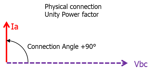
- (Angle of the) Relay Connection
The angle by which the current applied to the relay (at unity power factor) is relative to the voltage applied to the relay as the polarising voltage.
e.g. Ia and Vbc is a 90° or Quadrature connection. - Maximum Torque Angle (MTA) / Relay Characteristic Angle (RCA)
The angle by which the current applied to the relay must be displaced from the voltage applied to the relay to produce maximum torque
e.g. If the setting is MTA/RCA = +30°, it means that it is operating on the MTA/RCA when the actual current is leading the polarising voltage by +30°.
Hence, if it is a Quadrature connection Ia and Vbc,, when Ia is leading Vbc by +30°, therefore Ia is lagging Van by 60°, the system phase angle of Ia relative to Van is -60° at MTA/RCA,.
The discussion is in two parts - Phase Fault Overcurrent Relays and Earth Fault Relays. Both sections use an example of a phase-to-earth fault.
Phase Fault Overcurrent Relay Application
(Angle of the) Relay Connection
I can recall in my early years being annoyed that this first term could easily and inadvertently be called “Relay Connection Angle” – whilst that is understandable, as an acronym, that can easily be confused with RCA being officially the Relay Characteristic Angle as the electronic relay equivalent of MTA!!
So please be careful when referring to the “Angle of the Relay Connection” versus the "Relay Characteristic Angle"
Considering this “Angle of the Relay Connection”, Sonnemann defines four possible connections of voltage and current to the relay.
The "old school" electromechanical rotating induction cup directional elements, e.g. the GEC CCD directional cup unit and CDD combined directional and overcurrent/earth fault, were physically "per phase" elements so you had to be very specific with the CT and VT wiring to get the right inputs to each element.
With modern multifunction devices with the 3 phase-to-neutral voltage connections and the three phase currents, effectively every "connection" option is available to the directional element as required by setting.
However if we consider what are the required inputs to a particular directional calculation for one phase, we can consider those inputs in the generic sense of a "connection".
If we just consider the A‑phase directional overcurrent element, with
- zero degrees of the Van phasor at the 12 o’clock position
and - unity Power Factor
we get the following four connections to a directional element for the A phase.
NOTE: at this stage we have not yet determined the required MTA/RCA for the required protection zone!
Type | System Phasors | Connected Phasors |
|---|---|---|
90° or Quadrature Current: Ia Voltage: Vbc | Figure 1 |
Figure 2
Figure 3 |
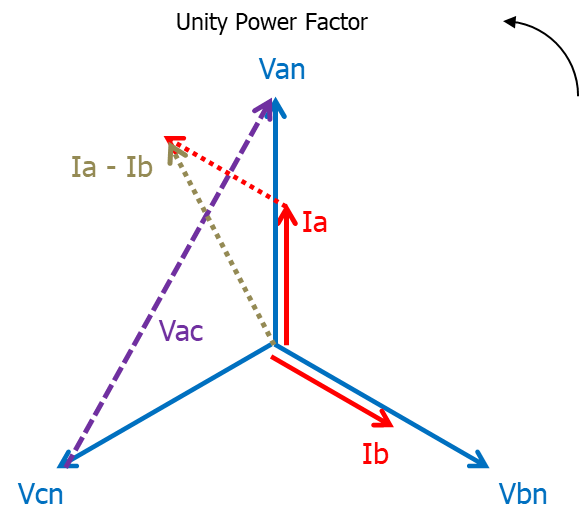
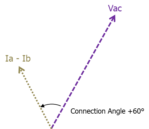
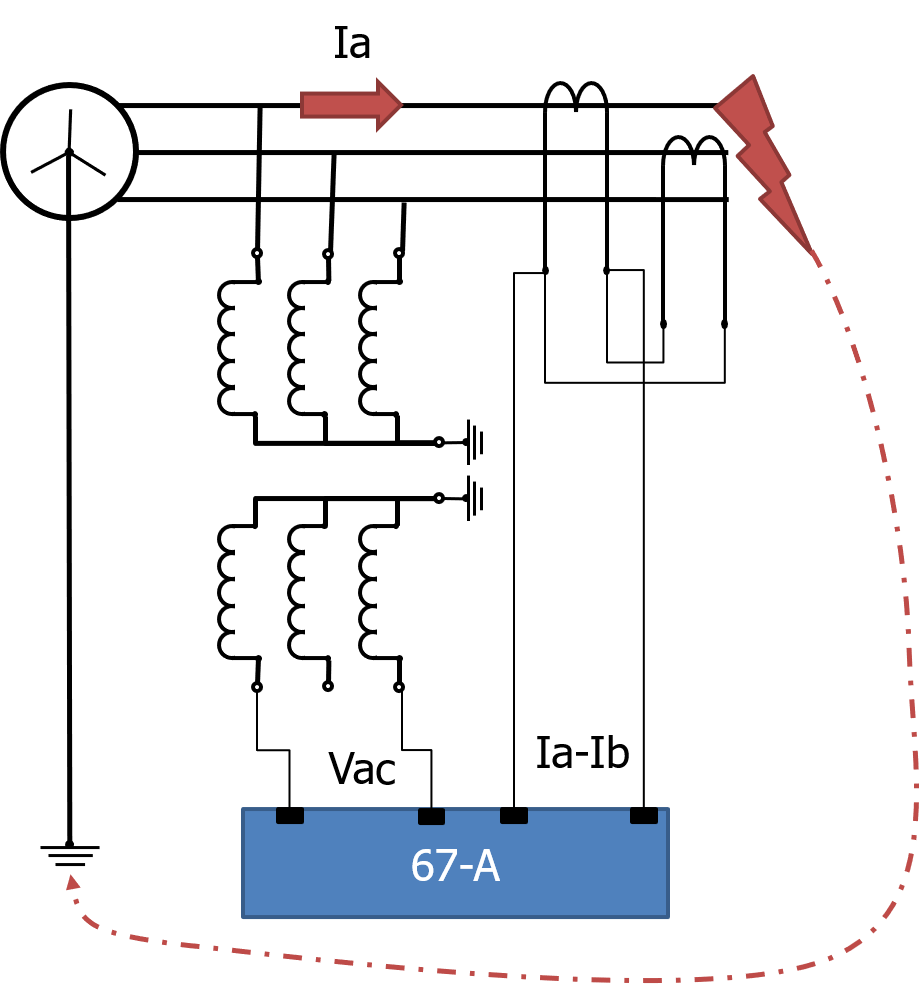
60° Type 1 Current: Ia – Ib Voltage: Vac (This CT arrangement | Figure 4 |
Figure 5
Figure 6 |
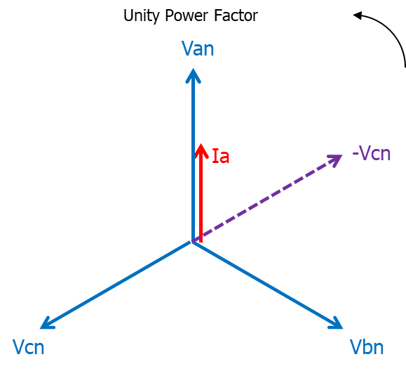
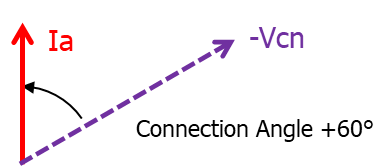
60° Type 2 Current: Ia Voltage: -Vcn | Figure 7 |
Figure 8
Figure 9 |
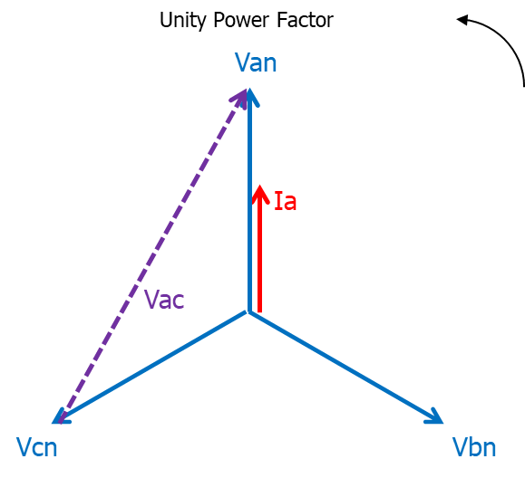
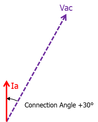
30° Current: Ia Voltage: Vac | Figure 10 |
Figure 11
Figure 12 |
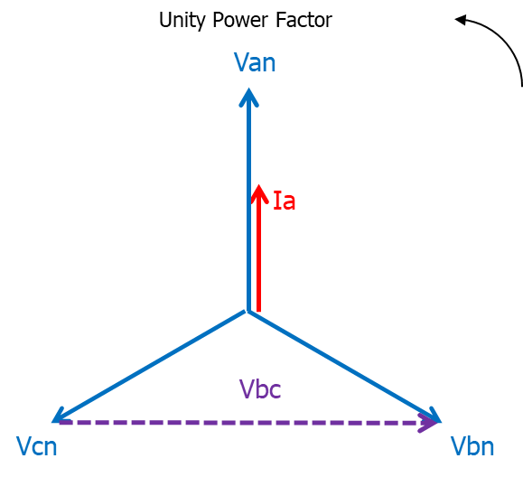
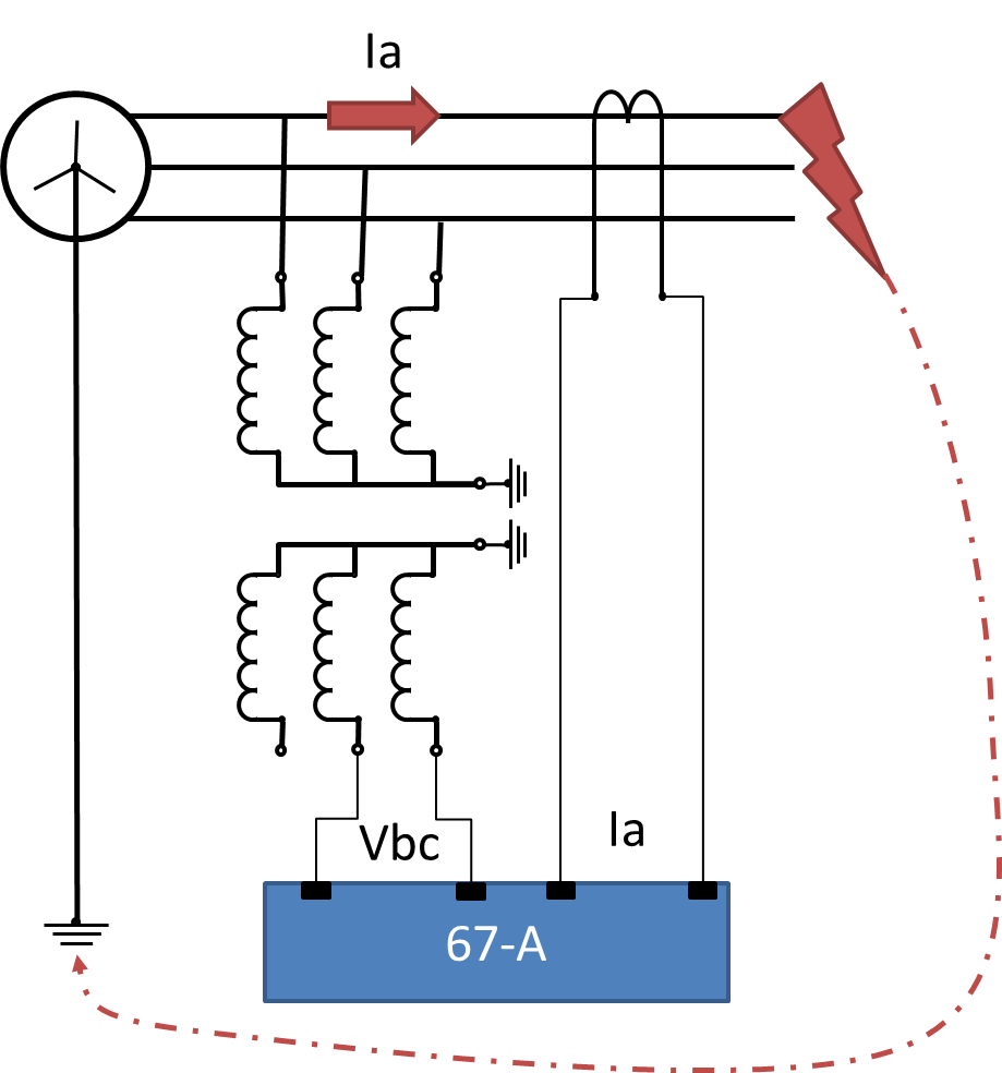

As most texts would agree, the most common and practical form is the 90° Quadrature Connection for various technical reasons of sensitivity as described by Sonnemann. Whilst I have shown the direct physical connections for the various directional options, (numerical relays can make the changes by settings), the remainder of this dissertation is based on Quadrature Connection as per Figure 3 connections.
Maximum Torque Angle (MTA) / Relay Characteristic Angle (RCA)
MTA and RCA are the same thing. You may find "oldies" like me refer to MTA, when we should really now be using RCA in most cases.
Maximum Torque Angle refers to electromechanical relays like the old GEC CCD and CDD where the cup mechanism literally rotated depending on whether the fault was seen in the operating zone.
The Torque refers to the force on the directional unit to swing one way or the other, which would then either allow or block the other relay function, i.e. a simple operating decision based on the fault being in the nominal range -90° to +90° of the MTA. The “torque” was important as at low values of voltage, the operating zone would collapse inwards at the outer boundaries centred at the MTA.
However but even at say 80° from MTA, it would still swing in the ring direction.
RCA was introduced as the new term for electronic relays because there was no mechanical torque inside the relay. This also means that the effect of low voltages on the ± degree range of the operating zone is much reduced. Nevertheless, the need to define the centre of the operating zone remains.
This second term of MTA/RCA is a little tricky in the wording used in the above definition:
“The angle by which the current applied to the relay must be displaced from the voltage applied to the relay to produce maximum torque”
In the Quadrature Connection, we know what voltage is applied, that is Vbc
So for a +30° RCA, we have to place a fault current phasor Ia’ at +30° relative to Vbc …. Note: it is NOT relative to Va
So MTA is when Ia’ is here
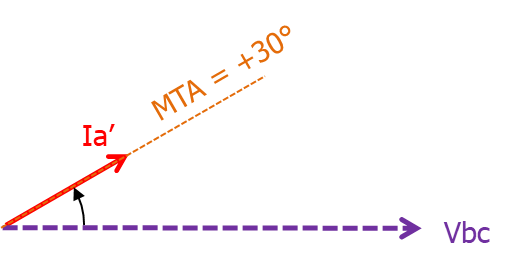
Figure 13
So what that means is the current Ia’ is effectively at 60 lagging from the Va phasor, i.e. it is 0.5 power Factor lagging
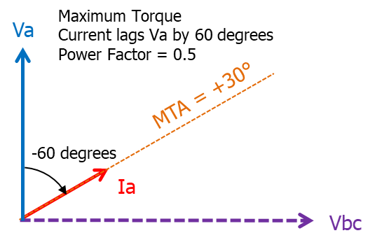
Figure 14
Hence MTA of +30° is achieved when the system Phase Angle = -60° i.e. phase current Ia lags phase voltage Vn by 60° i.e. at Power Factor 0.5 lagging.
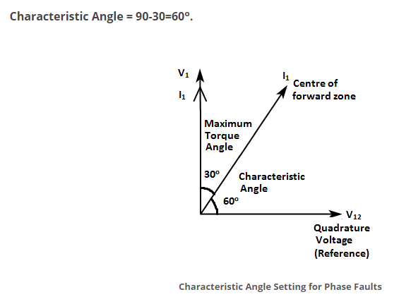
Unfortunately due to printing fonts &/or typo errors, some texts refer to this Quadrature connection with 30° MTA/RCA which may appear as:
90°-30°
The dash can be mis-interpreted as a MINUS sign, implying the MTA/RCA is -30° which is not correct.
However this dash is not a minus sign, but is intended to be merely a text separator between the two angles and hence is intended to be read as being “90° connection with a +30° polarising voltage rotation”.
It may be better to reference this using a colon for better clarity:
90° ; 30°
There is some possibility of confusion due to the official MTA/RCA definition uses a current compared to a voltage, but it is not our usual sense of such relativity which is the phase angle of Ia with respect to Va,
This is somewhat evident in the text book “Protective Relays: Principles and Applications” by Blackburn and Domin ISBN 10-1-57444-716-5 and ISBN 13-978-1-57444-716-3.
In Table 3.1, connection number 5 as Ia and Vbc is referenced as a “90° -60°” connection
But you will see in the definitions in the preceding paragraph that the angle of -60° (and it is correctly a MINUS 60 in this definition) is
“the angle by which the system current lags the system voltage”
i.e. they use PHASE ANGLE, not MTA/RCA to define the arrangement .. it is still an accurate identification of the arrangement but just using different definitions based on the usual terminology of current with respect to voltage as being the System Phase Angle from which we calculate Power Factor.
This dash in this instance is truly a minus sign is a clear confusion between the previous note where the dash in "90°-30°" is specifically NOT a minus sign.
At the risk of being presumptuous of “redefining the entire world”, I would suggest to re-word the definition of MTA/RCA without reference to current, after all it is all about defining the location of the polarising voltage with respect to the applied voltage as follows:
“The angle by which the polarising voltage of the relay leads the applied voltage to the relay”
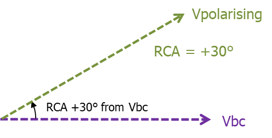
Figure 15
Now that would seem to make more sense that you get “maximum torque” when the connected current is in phase with Vpolarising.
Perhaps the following comparison examples will help clarify the terms.
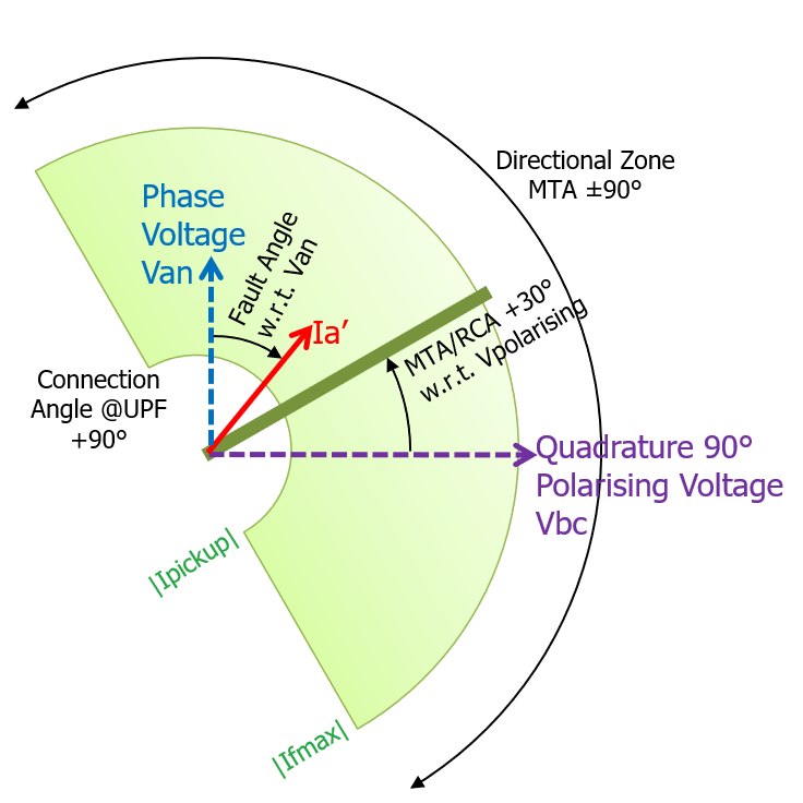
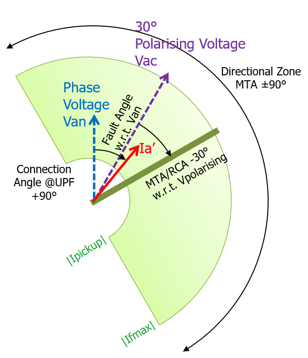
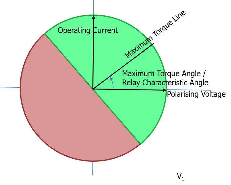
Consider a Directional Overcurrent element with a 90° quadrature connection.
It has a certain pickup current magnitude that the red current phasor must exceed to operate .. that is the smaller semi-circular boundary.
The red phasor magnitude by definition cannot exceed the max fault current at that location .. that is the outer semi-circular boundary.
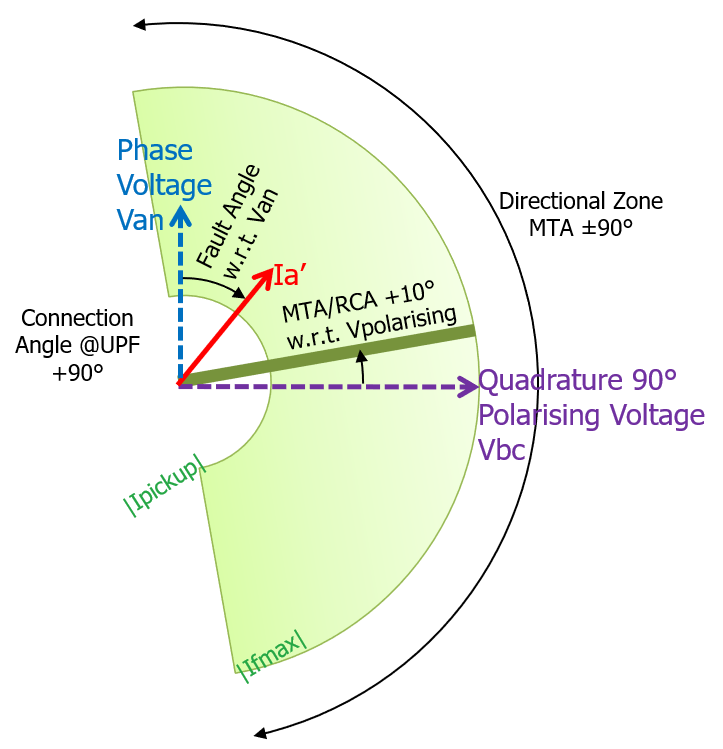
It also has a setting for the MTA/RCA .. the two examples are for +30° and +10° respectively (why 10° .. no reason, just to demonstrate!) .
The zones of operation are therefore bounded by ±90° of the respective MTA/RCA and referenced RELATIVE to the POLARISING VOLTAGE.
If the red current phasor falls with the green zone, the protection will operate.
| 90° Quadrature Connection (Ia and Vbc) | |
|---|---|
| MTA/RCA = +30° (PLUS 30°) | MTA/RCA = +10° |
Figure 16 |
Figure 17 |
However, as an alternative choice, if the polarising arrangement is not Quadrature, but Angle of Relay Connection is 30° (Ia and Vac), we get the same zones as follows by changing the MTA/RCA to suit:
| 30° Connection (Ia and Vac) | |
|---|---|
| MTA/RCA = -30° (MINUS 30°) | MTA/RCA = -50° (MINUS 50°) |
Figure 18 |
Figure 19 |

If you compare the two blue background examples, you can see the same zone coverage for the two different Connections by choosing appropriate MTA/RCA to suit.
Similarly, the two fawn background examples are the same zone coverage according to the Connection Angle and the MTA/RCA to suit.
Published Document Error 1
Some of the misunderstandings of these angles is due to typographical formatting in published documents.
An example of this is the well known PRAG/NPAG/PAAG published at various times by GEC, Alstom, AREVA, Schneider and GE.
If we have a look at the 1975 Edition 2, section 9.17.6 (see Figure 20) has two examples titled:
90°-30° characteristic (30° MTA)
90°-45° characteristic (45° MTA)
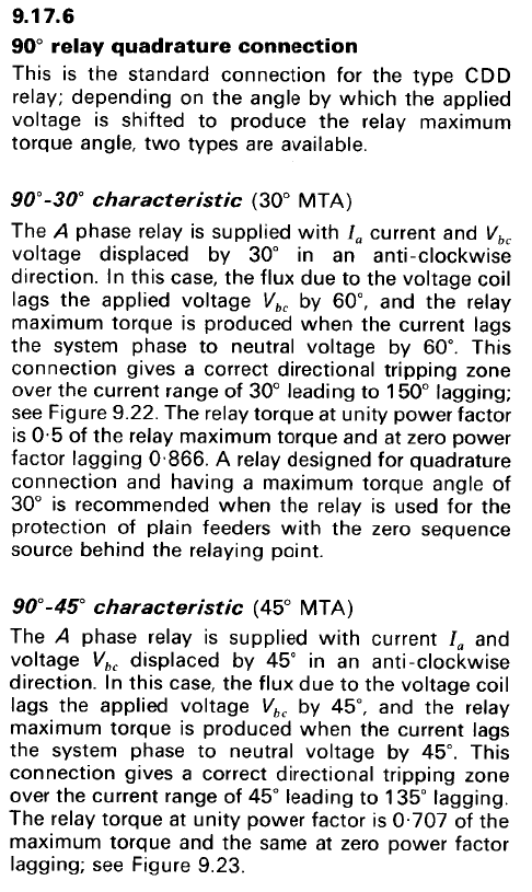
Figure 20 PRAG 1975 edition 2
Some others have ERRONEOUSLY simplified this apparent numerical reference as a MINUS sign and therefore to simply be "60°" and "45°".
But not so!!
The printed "-" dash is NOT a mathematical MINUS sign ... it is just a text separator!!
"90°-30° characteristic (30° MTA)" is short-hand publishing notation for:
"90° Quadrature connection with a PLUS 30° MTA/RCA relative to the Vbc Polarising Voltage"
This becomes clear(er) when you read the first sentence in each example:
The A phase relay is supplied with Ia and Vbc voltage displaced by 30° in an anti-clockwise direction. ... the relay maximum torque is produced when the current lags the system phase to neutral voltage by 60°.
"90°-45° characteristic (45° MTA)" is short-hand publishing notation for:
"90° Quadrature connection with a PLUS 45° MTA/RCA relative to the Vbc Polarising Voltage".
This becomes clear(er) when you read the first sentence in each example:
The A phase relay is supplied with Ia and Vbc voltage displaced by 45° in an anti-clockwise direction.
If we go back to the previous 1966 Edition 1 of the PRAG, the title "90°-30° characteristic (30° MTA)" was actually segregated in two paragraphs:
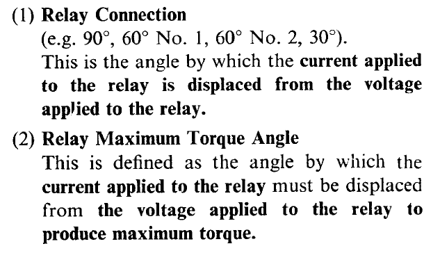
Figure 21 PRAG 1966 edition 1
As you can see, the 'clarity" of this two-part reference is lost when it is "simplified" for "publishing purposes" into something which looks mathematical: "90°-30° characteristic (30° MTA)".
Perhaps these short hand representations should have said something like:
90° Connection : +30° MTA/RCA
or
90° Connection with +30° MTA/RCA
Bottom Line of this Warning:
![]() Please be careful of short hand publishing typographical formatting!
Please be careful of short hand publishing typographical formatting!
Published Document Error 2
A further example of possible "terminology confusion" ...
A somewhat old electronic relay - the ASEA RXPE 42, defined its overcurrent relay as a "-30° directional overcurrent".
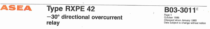
Figure 22
However the text of that brochure goes on to say
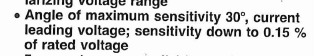
Figure 23
This current leading voltage reference seems to be a PLUS 30 degree reference.
It then goes on to refer to MINUS 30 degree characteristic angle 🤦♂️🤷♂️
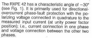
Figure 24
and the diagram shows the voltage reference as effectively Vbc
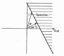
Figure 25
Consequently if maximum sensitivity is current leading the reference Vbc voltage by 30, then the current lags the phase-to-neutral by 60 degrees.
Published Document Error 3
I have also recently come across a technical web site which states that the MTA and the RCA are two different things either side of the Maximum Torque line.
They have fallen into the trap as per the PRAG typographical error mentioned above of thinking that "90 - 30" is a mathematical formula 😞👎
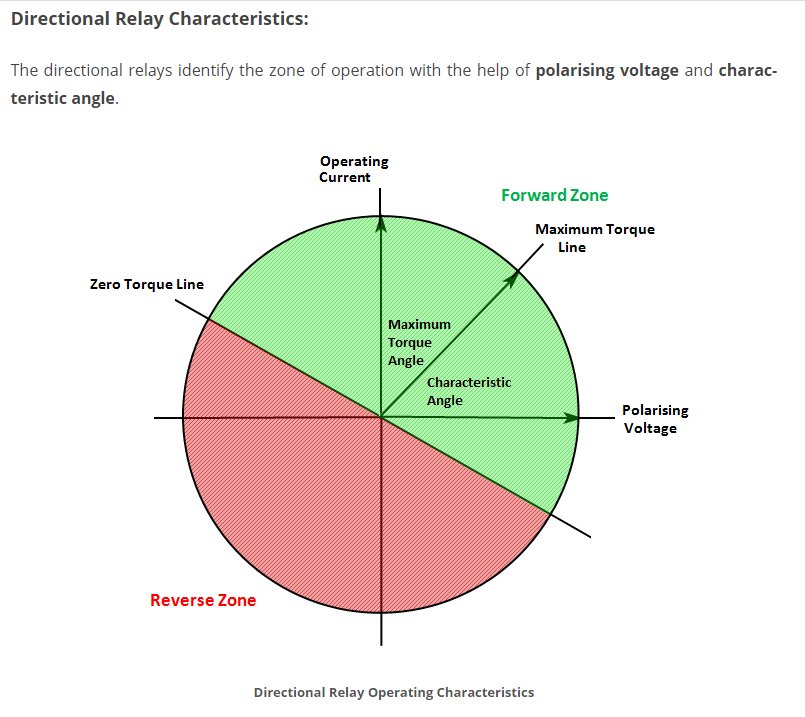
The corrected diagrams would be
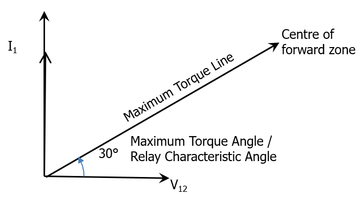
I am hoping they will heed my corrections
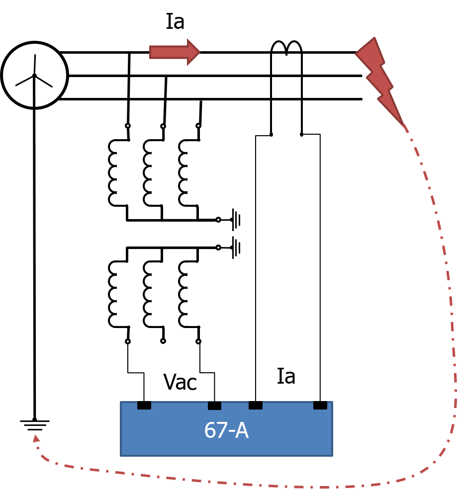
Earth Fault Relay Application
The trick there is that the zero sequence directional element needs Vo and In as the connected quantities. Clearly there is no "angle of connection" as V0 would be zero in a balanced load un-faulted condition.
The Van voltage phasor will reduce in magnitude due to the fault to earth and shift slightly yielding the system voltage phasors and the resultant V0 output of the delta winding VT as follows:
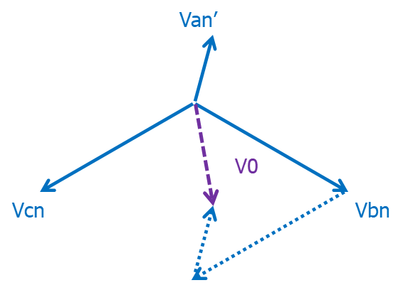
Figure 26
With the extreme short circuit right at the VT terminals, Van would be zero so V0 would be pointing straight down.
Also to note is that relative to the TF winding, Ia is flowing away from the TF and In is flowing towards the TF. Hence In = –Ia.
In = 3 x I0
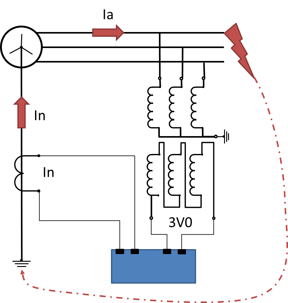
Figure 27
The inputs to the directional earth fault element need to be V0 and I0
As per Figure 27, we can get V0 from an open delta VT ... the output of that is by definition Va + Vb + Vc = 3 x V0
As for the zero sequence current, we can either use the direct neutral CT as per Figure 27, or the residual connection of the three line CTs connected in Holmgren, or a Core Balanced CT, or opposite of the A phase current since I0 = In/3 = -Ia/3.
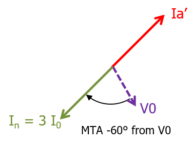
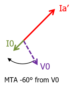
In any case, we now see that the Zero Sequence Current as the directional element applied current is LAGGING the Polarising V0 voltage.
Hence Earth Fault MTA/RCA would generally be expected to be NEGATIVE angle with respect to the Polarising quantity.
Figure 28 |
Figure 29 |
.
Copy this permanent link to this page: https://rhconsult.tiny.us/2as8v9me
Contact Me
A phone call is nearly always welcome depending on the time of night wherever I am in the world.
Based in Adelaide UTC +9:30 hours e.g.
| April-September | Noon UK = 2030 Adelaide |
| October-March: | Noon UK = 2230 Adelaide |
Mobile + 61 419 845 253
Extra Notes:
No Waiver, No Licence:
Rod Hughes Consulting Pty Ltd accepts no direct nor consequential liability in any manner whatsoever to any party whosoever who may rely on or reference the information contained in these pages. Information contained in these pages is provided as general reference only without any specific relevance to any particular intended or actual reference to or use of this information. Any person or organisation making reference to or use of this information is at their sole responsibility under their own skill and judgement.
This page is protected by Copyright ©
Beyond referring to the web link of the material and whilst the information herein is accessible "via the web", Rod Hughes Consulting Pty Ltd grants no waiver of Copyright nor grants any licence to any extent to any party in relation to this information for use, copy, storing or redistribution of this material in any form in whole or in part without written consent of Rod Hughes Consulting Pty Ltd.