Current Transformer P Class for Differential Protection
- Rodney Hughes
| Rod Hughes Consulting General Web Site | Applications Home | Innovations and Solutions Home | A bit about Rod Hughes |
|
|---|
Note - if the navigation pane on the left of this window is not visible, click the 2-pane icon on the top bar
I always recommend any differential protection application should use IEC 61869-2 PX class CTs.
This is because PX class effectively defines the construction of the CT to minimise false differential currents that may lead to incorrect tripping.
However there are occasions where such "freedom of choice" of the CT class and specification are not possible, or just the exact application was unknown at the time of procurement e.g.:
- bushing CTs on transformers
- high and low voltage TF CTs associated with the switchgear.
- Low voltage (e.g. 11 kV) metal-clad switchgear often has limitations on the CT compartment size and hence large PX class CTs can become difficult to accommodate.
Overcurrent or impedance relays require that the CTs must not saturate for the max fault current .. or at least up to the rated Accuracy Limit Factor required for the characteristic.
So sometimes there is a desire to use P class CTs in differential applications for one reason or another.
My recommendation is to resist this pressure for an "easy way out"!
General CT requirements
Overcurrent or impedance relays require that the CTs must not saturate for the max fault current .. or at least up to the rated Accuracy Limit Factor required for the characteristic.
HiZ diff i.e. CTs connected in Merz-Price Circulating Current arrangement require that the CTs can force current through another saturated CT in order prevent/minimise potential “false differential” currents.
But even so they WILL SEVERELY SATURATE for internal faults even though the fault can be the same magnitude as the Through Fault literally on the “other side” of the CT.
The relay must therefore be specifically designed to operate for heavily saturated “shark fin” waveforms.
LoZ diff has each CT is connected to a unique input to the diff relay typically as Holmgren connection. As such they don’t need to force current through another saturated CT as in HiZ.
Modern LoZ diff relays usually have the ability for CT ratio selection, power TF delta/star correction, tap changer differences on the power TF ….
Hence they have bias settings to cater for “some non-ideal matching” of the CTs
e.g. if the CTs are not “perfectly matched” to provide the same output for the same through fault current, the bias slope “hides” the problem to some extent by de-sensitising the setting.
But note the setting is de-sensitised for increasing current.
Some would say the difference between HiZ and LoZ relays “allows a less stringent” approach to CT selection for LoZ than for HiZ applications that would "allow" use of P class CTs.
In most cases, I would disagree!
I certainly disagree if very careful analysis has not been undertaken!
CT selection must ALWAYS be done with careful consideration of the effect on the protection system.
In the case of differential protection, this inherently favours class PX CTs.
Can you use P class CTs for differential application?
There is no "magic" difference between a P class and PX class CT. It i s"just" the way we describe it in a different format of the specification terms.
So is it possible to use a P class CT for differential applications?
One possibility is to do a full test on the CT wit P class definition and derive an equivalent set of PX class terms t describe the CT, and go from there.
But what can we do prior to being able to test the P class CT to identify how it would perform in a differential application?
All diff relay CT selection should be approached with a high degree of care to minimise “false differential current” when the current is a through current load or through current fault.
The objective may be to detect faults as low as say 5% of rated current.
Let's consider a simple example of two P class CTs in a low impedance application with the same specification except for rated burden.
| CT Spec | CT rated secondary | Rated Burden | Class | Accuracy Limit Factor | |
|---|---|---|---|---|---|
| CT #1 | 1 A 5VA 10P20 | 1 A | 5 VA | 10% | 20 |
| CT #2 | 1 A 10VA 10P20 | 1 A | 10 VA | 10% | 20 |
So far we have CTs that would "nominally" seem to be suited .. except that we want a target setting of 5% of rated with a 10% accuracy at the ALF.
According to IEC 61869-2, a class 10P CT is max ±10% accurate at the ALF and is max ±3% at rated current.
Knowing that the actual burden is much less than the rated burden, say just 1 VA, it would seem at first glance to be "OK" that these are used for the differential application.
We must first check how these CTs actually perform
First considering the rated performance of each.
P class CTs do have the possibility of a variation in TURNS RATIO in order to achieve a certain accuracy at the Accuracy Limit Factor.
However for the sake of this analysis, lets assume the CT TURNS RATIO exactly matches the CURRENT RATIO
The Accuracy of the CT is then largely determined by the Excitation Current giving a ± error output, i.e. the output current could be lower or higher than expected.
We can also make some assumptions about the Magnetising Curve minimum Kneepoint Voltage simply because we know the CT must not have saturated in order to remain within required accuracy.
Hence we can derive a minimum value of the Kneepoint Voltage for each CT
| ALF Amps | Rated Burden | rated error @ ALF | Low Output | High Output | Ek min | |
|---|---|---|---|---|---|---|
| CT #1 | 20 A | 5 Ω | 2 A | 18 A | 22 A | 100 V |
| CT #2 | 20 A | 10 Ω | 2 A | 18 A | 22 A | 200 V |
So both CTs seem to perform in a similar way, one with a potentially larger kneepoint voltage.
Excitation Current is determined by the output current of the CT and the burden connected to the CT in accordance with Ohm's Law.
That is effectively what is measured when you do a Magnetising Curve of the CT - you apply terminal voltage and measure the excitation current.
But in service, the Terminal Voltage is given by Ohm's Law as
Vterminal = Iout x Rb
So what about CT accuracy at less than rated current?
Without specifically doing a Magnetisation Curve test, we have no actual value of the Excitation Current.
Suffice to say that down near the Ankle Point of the CT, accuracy percentage is severely dominated by the Excitation Current.
However for the sake if this analysis, lets assume the Excitation Current is linearly proportional all the way to zero terminal voltage (zero output current).
Hence we can get a rough estimate of the accuracy (or inaccuracy) of the CT output for a given burden.
So instead of Rated Burden, we have a Low Impedance Differential relay connected with total connected burden of just 1 Ω.
At first glance, that looks fine because the burden is way below the rated burden of both CTs, so "surely" the diff relay will be "happy".
But what is the operating point of these two CTs with a lower burden and both CTs nominally producing the same output current of 20 x rated?
Ohm's Law applies again.
Not surprisingly, as both CTs are trying to produce the same output current into the same burden, their terminal voltages are the same.
BUT that means their Excitation Current is different.
We therefore have to consider the comparison of the Excitation Curves, albeit ignoring the effect of the Ankle Point>
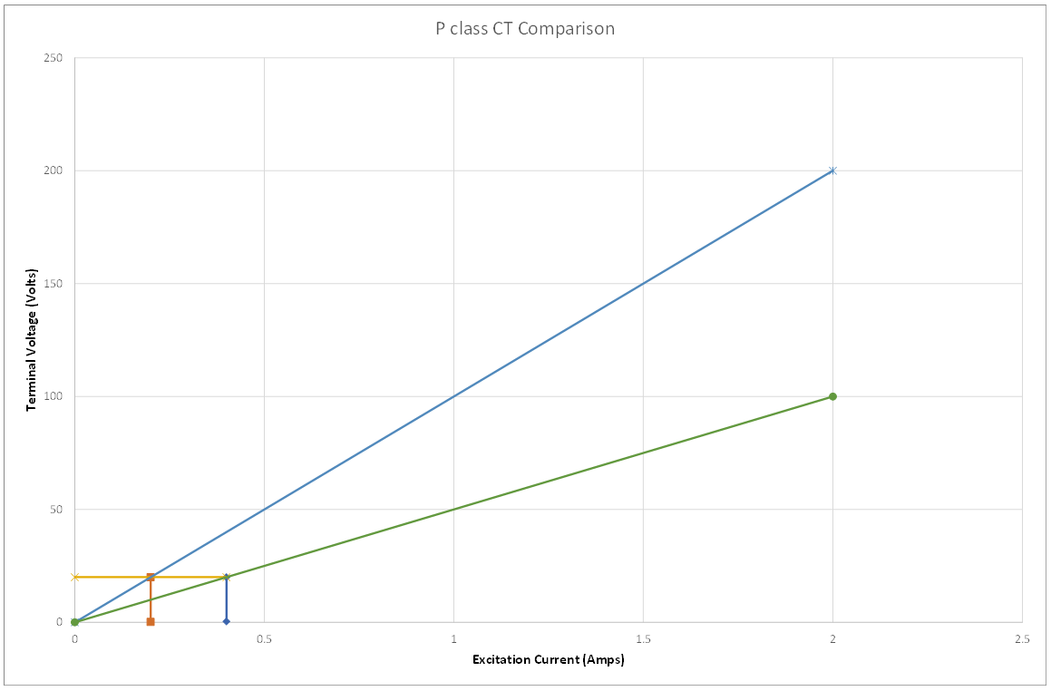
We can now see the effect of the different Excitation Currents on the output of the two very similar P class CTs:
| Actual Burden | Vterm actual | Ie actual | Iout Low Actual | Iout High Actual | |
|---|---|---|---|---|---|
| CT #1 | 1 Ω | 20 V | 0.4 A | 19.6 A | 20.4 A |
| CT #2 | 1 Ω | 20 V | 0.2 A | 19.8 A | 20.2 A |
We can see that the "rated false differential current" is the difference between the two actual Excitation currents being "just" 0.2 A.
But the overall "range of false differential current" is from highest output of one CT to the lowest output of the other, being 0.6 A !!
So we MUST make sure the relay does not operate for 0.6 A (60% of rated) false differential current for a through fault current condition, noting we actually wanted to be able to detect a real fault of 0.05 A (5% of rated).
That is just the bias we need to cater for P class differences.
Then you must add more bias for CT ratio mismatch, TF Tap change ....
So as you can see, simply selecting P class CTs for Low Impedance Differential is not as "less stringent" as we would first think!!
Copy this permanent link to this page: https://rhconsult.tiny.us/yckkx543
- Protection Systems Engineering
- IEC 61850 Engineering
I provide a range of courses for company-specific in-house training and occasional public invitation courses. Contact me for details.
Contact Me
A phone call is nearly always welcome depending on the time of night wherever I am in the world.
Based in Adelaide UTC +9:30 hours e.g.
| April-September | Noon UK = 2030 Adelaide |
| October-March: | Noon UK = 2230 Adelaide |
Mobile + 61 419 845 253
Extra Notes:
No Waiver, No Licence:
Rod Hughes Consulting Pty Ltd accepts no direct nor consequential liability in any manner whatsoever to any party whosoever who may rely on or reference the information contained in these pages. Information contained in these pages is provided as general reference only without any specific relevance to any particular intended or actual reference to or use of this information. Any person or organisation making reference to or use of this information is at their sole responsibility under their own skill and judgement.
This page is protected by Copyright ©
Beyond referring to the web link of the material and whilst the information herein is accessible "via the web", Rod Hughes Consulting Pty Ltd grants no waiver of Copyright nor grants any licence to any extent to any party in relation to this information for use, copy, storing or redistribution of this material in any form in whole or in part without written consent of Rod Hughes Consulting Pty Ltd.