Distance Protection - Under and Over Reach Terms
- Rodney Hughes
| Rod Hughes Consulting General Web Site | Applications Home | Innovations and Solutions Home | A bit about Rod Hughes |
|
|---|
Note - if the navigation pane on the left of this window is not visible, click the 2-pane icon on the top bar
Distance relays have been a mainstay of protection transmission lines for decades as they do not specifically require a communications bearer providing instantaneous protection for most of the line.
They also provide inherent back up with their zones overlapping the protection of the next line, and hence they are sometimes called "Stepped Distance Protection" - this is not unlike grading of Inverse Definite Minimum Time relays where the further you are from the source, the longer the relay operating time.
The ability of distance relays to operate in absence of a communication signal means they are often provided as a "back up" protection integrated into modern line differential relays which normally rely on the communications bearer.
Unfortunately there a few different ways or contexts for referring to the zone of operation and the means of operation as the "reach" of the relay which can lead to some confusion or misunderstanding of how they relate to each other. The common references are in the context of:
- Setting Under/Overreach
- Fault Under/Overreach
- Transfer Tripping using Permissive Under/Overreach schemes
1. Setting Under/Overreach - Zone Coverage
Distance relays typically have at least three Zones of protection typically set with their Zone 1 and Zone 2 reach somewhat similar to these principles:
Zone 1: ~80% of the impedance of the entire length of the line "busbar-to-busbar", or busbar-to-transformer bushings in the case of transformer ended lines
Zone 2: ~120% of the impedance of the entire length of the line "busbar-to-busbar", or at least into the transformer windings
Since Zone 1 does not cover the entire length of the line, it can be said that its reach (by design) is under the length of the line.
On the other hand since Zone 2 and 3 cover beyond the remote busbar, it can be said that their reach (by design) is over the length of the line.
It is easy to imagine then how these settings could be colloquially referred to as Underreaching settings or Overreaching settings applied by design.
2. Fault Under/Overreach - Impedance Seen
Distance protection uses measurements of system voltages and currents to calculate the impedance seen by the relay. The impedance seen by the relay is interpreted by the known ohms/kilometre of the conductor as the distance to fault. This determination of the impedance seen as distance to fault is known as the "reach" of the zone.
There are of course inherent accuracy considerations of the CT and VT errors and the accuracy of the relay itself. However the function of the measurement techniques within the relay also cause some changes to the "size" of the expected zone coverage itself such as polarised ground fault mho expansion.
However, various normal and inherent primary system conditions can significantly influence the voltage and currents presented to the relay which cause incorrect calculation of the impedance seen by the relay, i.e. the reach is different to the actual distance to fault. These issues include such conditions as:
- weak in feeds,
- varying source impedances,
- mutual coupling between parallel lines,
- non-homogeneous ground impedance along the route of the line,
- teed lines,
- hybrid overhead lines/underground cables
- series compensated lines
- ...
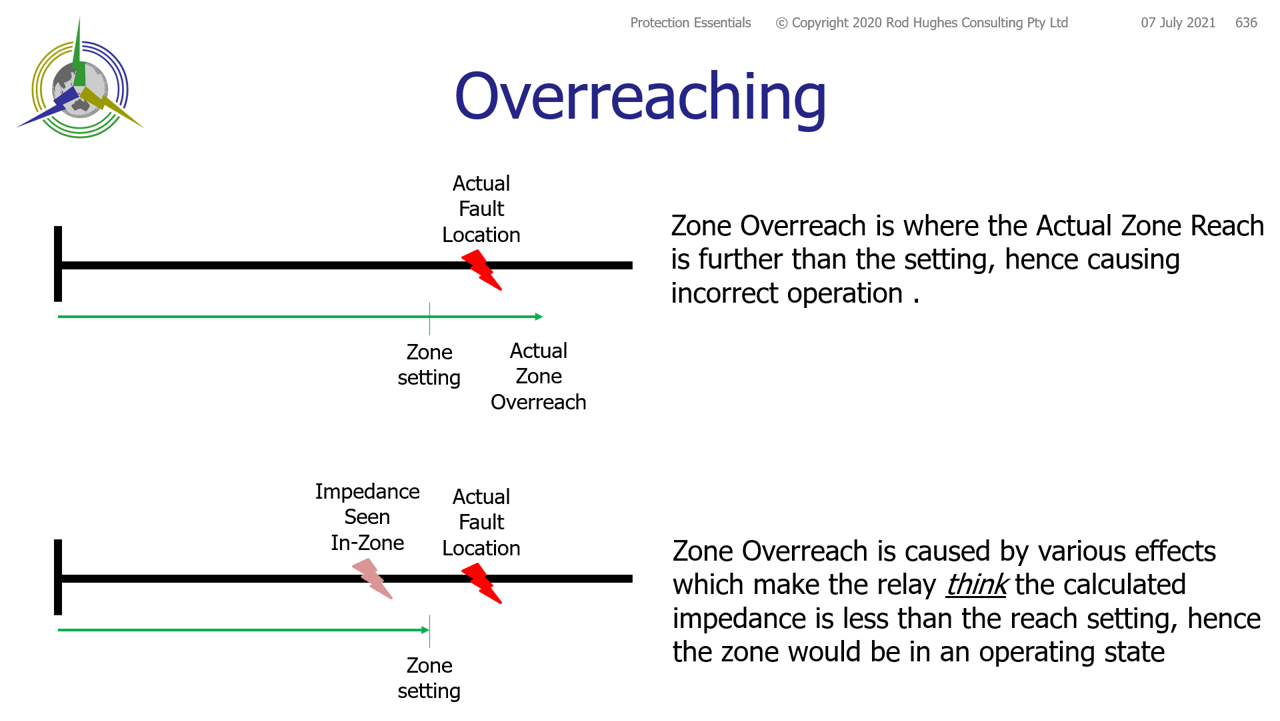
According to the system conditions at the time of the fault, any distance relay Zone may either Overreach or Underreach.
In this context we are referring to the actual primary distance-to-fault impedance, versus what the relay calculates, i.e. thinks the measured impedance is.
Fault Overreach is where the measured/seen impedance to the fault is less than the actual value.
The effect of Overreach is that as the impedance is seen less than the actual value, the Zone element may "think" the impedance is within the setting zone i.e. the zone element operates when it shouldn’t e.g. polarised ground fault mho expansion characteristic means the zone expands causing the zone to operate for a fault that, based on the settings alone, it should not operate for.
Note: ANY element may suffer Overreaching.
Zone 2 and 3 elements are set to reach beyond the remote busbars. However they should not be classed as "overreaching elements" (in the sense of reaching over the remote busbars) as it is just a function of setting.
Overreach is a significant problem for distance protection as a Zone 1 element overreach may extend onto and beyond the remote busbars causing an incorrect discrimination, or at least simultaneous operation to the protection closer to the fault at the remote substation.
Overreach can be expressed by the formula and expressed as Percentage
(ZF - ZR)/ ZR
Where:
ZF is the effective reach provided by the relay
ZR is the relay reach setting
We would then say for a particular set of power system conditions that the relay would overreach by X% and therefore potentially operate when it should not
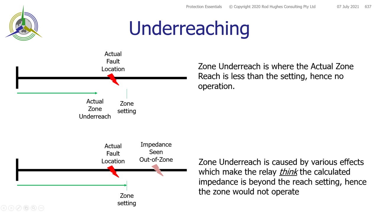
Fault Underreach is where the measured/seen impedance to the fault is more the actual value.
The effect of Underreach is that as the impedance is seen more than the actual value, the Zone element may "think" the impedance is beyond the setting of the relay i.e. the zone element fails to operate when it should
Note: ANY element may suffer Underreaching.
Zone 1 elements are set to reach typically ~80% of the line length. However they should not be classed as "underreaching elements" (in the sense of a setting under the total line impedance) as it is just a function of setting.
The lack of operation for a fault may lead to slower fault clearance by other protections.
Overreach can be expressed by the formula and then expressed as Percentage
(ZR - ZF)/ ZR
Where:
ZF is the effective reach provided by the relay
ZR is the relay reach setting
We would then say for a particular set of power system conditions that the relay would under reach by X% and therefore potentially NOT operate when it should.
3. Transfer Tripping Permissive Under/Overreach - Complete Line Coverage
There are many factors of the CT/VT accuracy, the relay accuracy itself as well as the varying system conditions that mean we cannot assume that the impedance seen by the relay is 100% accurate relative to the location of the fault. As such we have to consider a relay at the "local" end seeing a fault on the far end busbars or beyond. Such a far-end fault should NOT cause operation of the local distance relay instantaneous Zone 1 element as that would be incorrect discrimination with the far end protection intended to clear that fault. Consequently Zone 1 elements are generally set with their reach to ~80% of the length of the line.
As Zone 1 only covers ~80% of the line, that leaves ~20% of the line only protected by the delayed Zone 2 element with an operating time of say ~0.4 seconds.
In order to obtain faster fault clearance of that far end of the line, it is necessary to employ a distance signalling scheme between relays at both ends of the line with their respective Zones "looking" towards each other. Other schemes use a blocking feature which is not discussed here.
The two common schemes are so called Permissive Overreaching Transfer Tripping schemes or Permissive Underreaching Transfer Tripping.
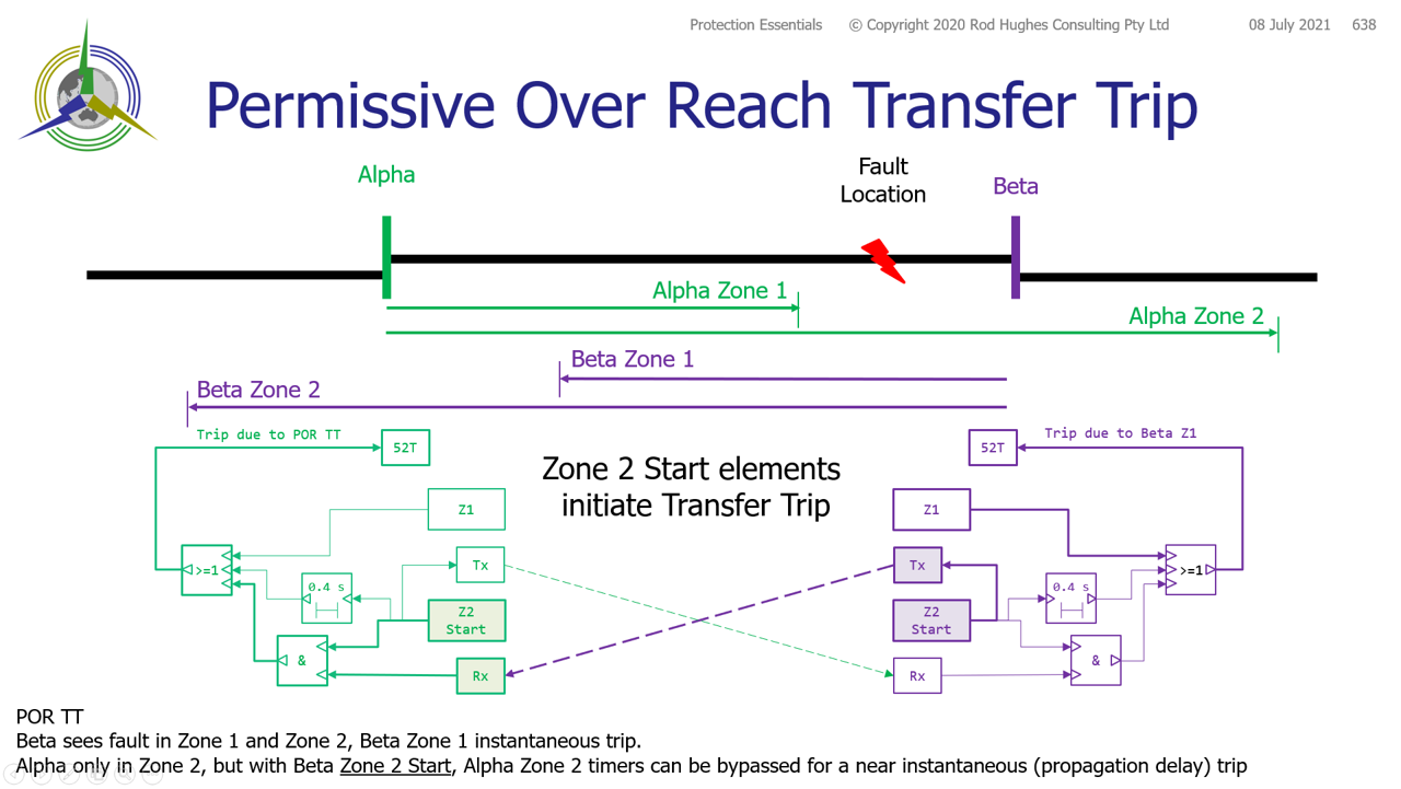
Permissive Over Reach Transfer Tripping (POR TT)
POR TT is where both ends exchange signals to "agree" that the fault is within their respective Z2 and so both can bypass their respective Z2 timers.
Definition: It is the Zone 2 elements that transmit/send their start signal to the remote end, i.e. initiate the Transfer Trip signal.
If the receive end has seen the fault, and it has also seen the fault in Zone 2, it will bypass its own Zone 2 timer for an instantaneous trip.
In the example, the fault is close to Beta end so it is beyond the reach of Alpha Zone 1.
Alpha has seen the fault its Alpha Zone 2.
Beta sees the fault in both its Zone 1 and Zone 2.
Beta trips instantaneously due to its Beta Zone 1.
Beta Zone 2 Start also initiates a signal transmit to Alpha.
When Alpha receives the signal from Beta, and as its own Alpha Zone 2 start has operated, the Alpha Zone 2 timer is bypassed causing an instantaneous trip at that instant, i.e. only delayed by the propagation time of the signal.
The elements involved in the POR TT decision are shaded for emphasis.
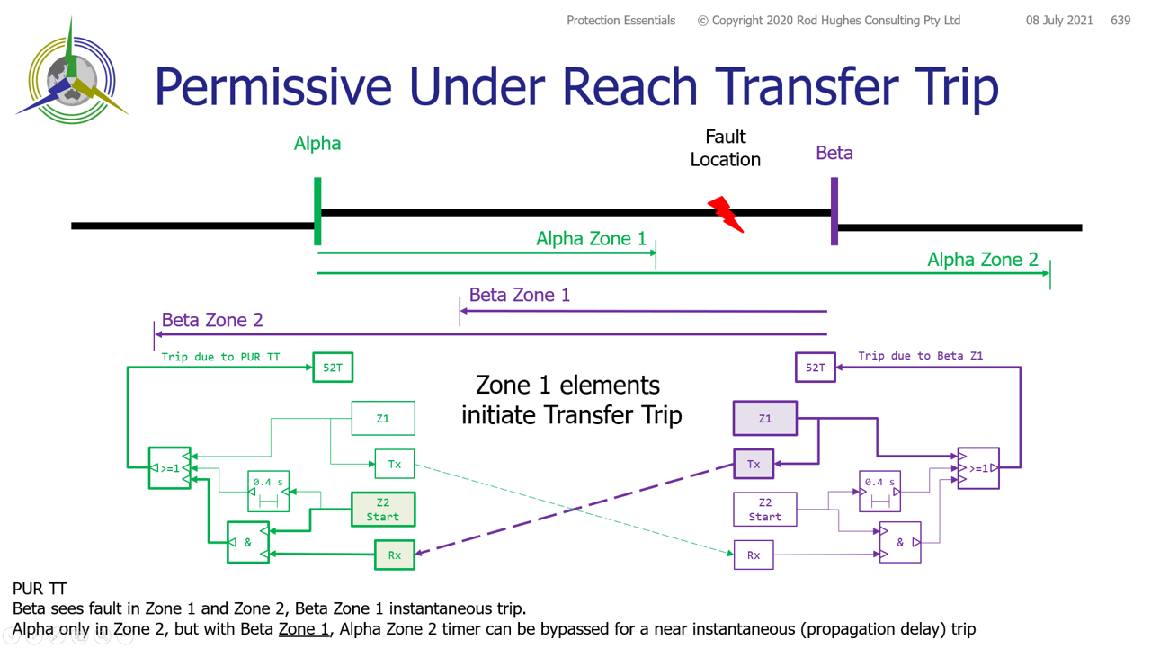
Permissive Under Reach Transfer Tripping (PUR TT)
PUR TT is where one end sees fault in Zone 2, the other end in Zone 1 so te exchange of signals allows the Zone 2 end to bypass its Z2 timer to trip near instantaneously - only delayed by the propagation latency of the Transfer Trip signal between the two ends.
Definition: It is the Zone 1 elements that initiate the Transfer Trip signal.
If the receive end has seen the fault, and it has also seen the fault in Zone 2, it will bypass its own Zone 2 timer for an instantaneous trip.
In the example, the fault is close to Beta end so it is beyond the reach of Alpha Zone 1.
Alpha has seen the fault its Alpha Zone 2.
Beta sees the fault in both its Zone 1 and Zone 2.
Beta trips instantaneously due to its Beta Zone 1.
Beta Zone 1 operation also initiates a signal transmit to Alpha.
When Alpha receives the signal from Beta, and as its own Alpha Zone 2 start has operated, the Alpha Zone 2 timer is bypassed causing an instantaneous trip at that instant, i.e. only delayed by the propagation time of the signal.
The elements involved in the PUR TT decision are shaded for emphasis.
- Protection Systems Engineering
- IEC 61850 Engineering
I provide a range of courses for company-specific in-house training and occasional public invitation courses. Contact me for details.
Contact Me
A phone call is nearly always welcome depending on the time of night wherever I am in the world.
Based in Adelaide UTC +9:30 hours e.g.
| April-September | Noon UK = 2030 Adelaide |
| October-March: | Noon UK = 2230 Adelaide |
Mobile + 61 419 845 253
Extra Notes:
No Waiver, No Licence:
Rod Hughes Consulting Pty Ltd accepts no direct nor consequential liability in any manner whatsoever to any party whosoever who may rely on or reference the information contained in these pages. Information contained in these pages is provided as general reference only without any specific relevance to any particular intended or actual reference to or use of this information. Any person or organisation making reference to or use of this information is at their sole responsibility under their own skill and judgement.
This page is protected by Copyright ©
Beyond referring to the web link of the material and whilst the information herein is accessible "via the web", Rod Hughes Consulting Pty Ltd grants no waiver of Copyright nor grants any licence to any extent to any party in relation to this information for use, copy, storing or redistribution of this material in any form in whole or in part without written consent of Rod Hughes Consulting Pty Ltd.