Testing IEDs and Functions
- Rodney Hughes
| Rod Hughes Consulting General Web Site | Applications Home | Innovations and Solutions Home | A bit about Rod Hughes |
|
|---|
Note - if the navigation pane on the left of this window is not visible, click the 2-pane icon on the top bar
You have probably heard it ... "IEC 61850 is hard to isolate .. we had to create proprietary logic and special GOOSE ...."
Regrettably even after 20 years of the Standard, that whinge continues in many places! 😞☹️
It is TOTALLY false and based on a LACK OF UNDERSTANDING!
The Working Group that wrote the Standard were power system engineers and technicians who know what happens in substations so isolation was a specific inclusion from Day One!
If only Users (of all types vendors, System Integrators, Asset Owners and Technicians) would read, and come to an understanding, of the Standard! Or at least ask for training! https://rhconsult.tiny.us/mwwkvw2z
Isolations
Consider any live substation.
When you are testing the X protection of Bay1, the Y protection and indeed the Fdr1 CB may well be in normal service as a live working substation and bay.
So when you are testing the Fdr1 X protection you do not want to trip the CB due to a particular test, nor do you want a X system CB Fail test to trip all the other feeders. 😬
So in the “good old wire-based days”, you would open the trip link from the X protection relay to the X CB trip coil.
The Y protection link would be left closed.
You would then open the Fdr1 X CB Fail link to the busbar multi-trip relay because you don’t want your Fdr1 testing to trip the busbar … well, not for this test anyway – other tests you may need to test a complete bus trip!
Here is a general d.c. wiring schematic for the X and Y protection systems for Fdr 1 and Fdr 2, together with the Busbar protection and its multi-trip relay 86X. It also shows the two Fdr 1 links that must be opened before you start testing.
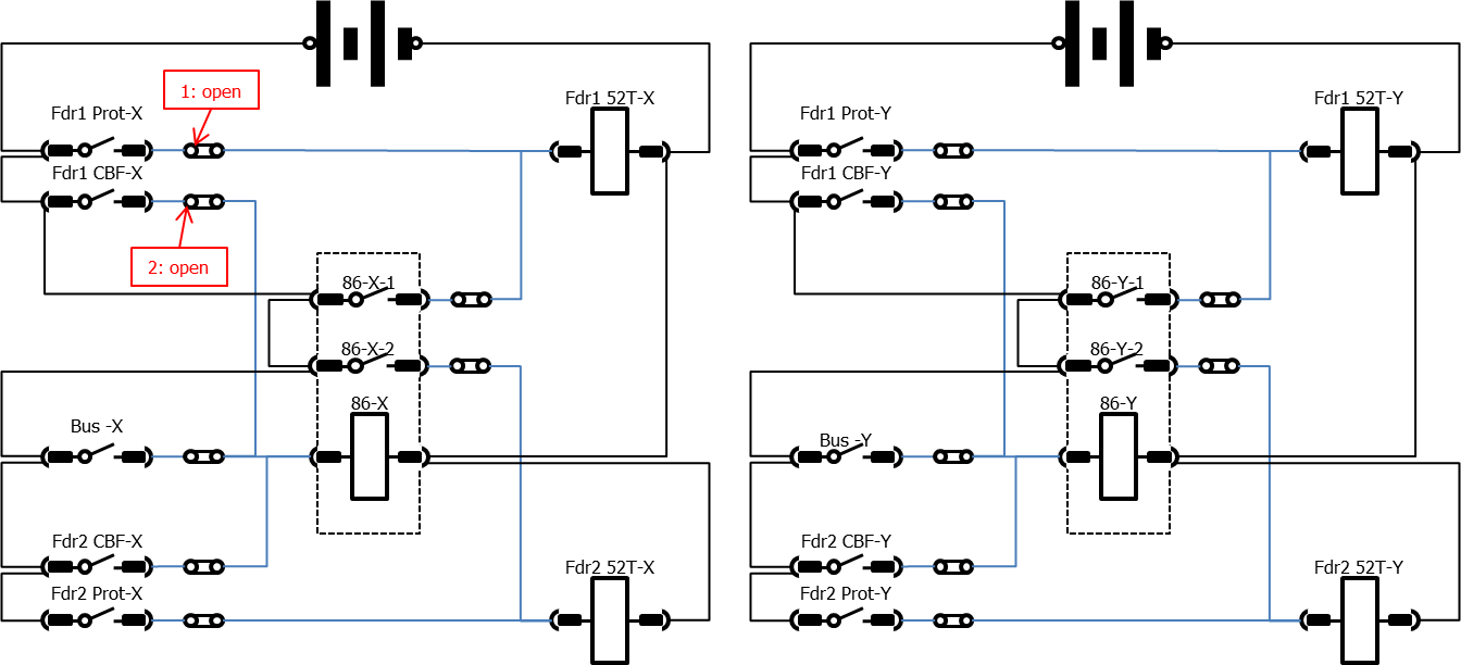
You would no doubt also open the Feeder1 X and Y Auto-reclose link to the CB close coil because you don’t want your testing of the Fdr1 protection to cause a trip or reclose of the Feeder1 CB.
Both the SCADA trip and close circuit may or may not be enabled, probably by the Local/Remote selector switch or other local/remote SCADA.
Hence no matter what you do to the DUT/FUT, you won’t cause an inadvertent trip of the Feeder1 CB. 👍👌😁
There are other associated functions such as the feeder measurements for Amps, Volts, Watts, vars, Frequency etc as measured by the DUT that probably don't need to be provided to the SCADA system during the testing process ..
However because the other Feeders are still in service, and indeed Feeder1 CB is still closed in service as well, you still need the X busbar protection to trip Feeder1 CB in the event of a bus fault !
Also as a result of a CB Fail condition on Fdr 2-to-n, their CB Fail detection (X and/or Y) still needs to cause Fdr1 CB to trip because it is a live busbar!
Consequently at least the Fdr1 CB Y trip coil needs to have the trip link for Busprot and CBFail left closed.
You would then short the CTs to the X protection relay and open up a link to allow you to inject current into the Fdr1 relay.
Same Principle, Different Mechanism
In the IEC 61850 world, we still need the same degree of control of allowing the XCBR to trip the CB for certain GOOSE received, whilst not tripping the CB for signals associated with the Device Under Test (DUT) or Function Under Test (FUT).
First to remember that IEC 61850 is a SYSTEM.
Everything remains listening to everything!
We never switch off the Publishing 📢 or the Subscribing 👂!
We just control what action the Subscriber takes when they receive the message, e.g.
- if your fire alarm went off NOW .. you would leave the building – the Fire Brigade would enter the building.
- But if we precondition you to know that the alarm in the next minute is a test, you do nothing, the Fire Brigade do nothing.
- Or we could precondition you that when the test alarm goes off, we want you to do a test evacuation, but still the Fire Brigade do nothing
- or we might still want the Fire Brigade to turn up.
THAT is what <<.Mod>> and <<.Beh>> is all about!
Proprietary solutions - TOTALLY Unecessary
Despite the definition of <<.Mod>> and <<.Beh>> in IEC 61850-7-4 Ed1, some System Integrators, even Asset Owners, have specified some sort of proprietary logic that puts the entire DUT/FUT into a test-state of their own making. This might be a push button on the front of the relay, or an external test‑block‑and‑plug wired to a digital input of the relay (apparently this makes the operators think they are still using “airgaps” in the circuit, or at least supposedly gives them a physical/visual indication that the test mode is applied ... even though the wire to the IED could be disconnected or the IED wrongly configured!).
I don't mind the choice of the physical interface for the operator to use - a button, a switch, a link, a menu ... they have to be comfortable with knowing what and how to do things when they walk into the substation .. preferably the same in every substation and for every combination of vendor devices (You may have seen that wire-based systems often had the isolation links laid out in a consistent sequence to minimise operator error).
However behind the physical control mechanism for the operator, in some/most cases, these proprietary solutions totally ignored the availability of <<.Mod>> and <<.q bit12>>.
A common approach has been inserting an individual bit in the GOOSE Dataset which was set to 1 when the operator pressed the relay push button or inserted the test plug.
Or the relay was sent some proprietary command to set controllable point in a GGIO LN (despite that could be an incorrect use of GGIO).
This bit was also referred to as a "test bit" in conflict to <<.q bit12>>.
Of course that also means you need some other proprietary logic in all the other IEDs to allow, or block, the use of the incoming GOOSE Dataset depending on the value of the quality test bit.
These arrangements are quite .. even severely .. complex, arguably dangerous or at least inappropriate, as they apply to the whole DUT, and ignores the requirement for some of the IED functions to be working normally.
Of course there is then a philosophical but very relevant discussion to be had that any test in that arrangement is testing the test-logic, not the normal operating-logic!
So lets set the record straight ...
IEC 61850‑7‑4, even from Ed1, achieves the right combination of operating states through the combination of the <<.Mod>> Data Object associated with every Logical Node plus the value of the so-called “test bit” in the string of values that represent the quality Data Attribute of the source Logical Node.
This is described originally in IEC 61850-7-4 Ed1 in the explanation of <<.Mod>> in Chapter 6 Data name semantics.
Six years later, IEC 61850-7-4 Ed2 went one step further in the explanation with Annex A and in particular Table A.2 .. because so many were whinging there was no isolation facility.
So, ever since IEC 61850-7-4 Ed1, you can send an MMS command to set the <<LLN0.Mod>> of each LN individually, thereby changing its <<.Beh>> and hence how it behaves during testing, and consequently how other LNs behave when receiving GOOSE from DUT/FUT.
Therefore there has always been a complete standard "Isolation" mechanism provided in the Standard!
I'll throw out one "excuse" for not understanding what was built in to the Standard. The GOOSE header test bit.
Ed 2 got rid of the erroneous/conflicting reference in Ed1 to what colloquially became known as “the test bit”!
IEC 61850-8-1 Ed1 Table 56 described the header to a GOOSE message as having a “Test bit”.
There was always also a test bit in the 13-bit string for quality.
IEC 61850-8-1 Ed2 Table 79 changed the name of that "Test bit" in the HEADER to “Simulation” .. that SIM flag identifies the source of the GOOSE message as a test set rather that the in service IED.
We still have <<.q(test)>> as the bit controlled as it always has been by the value of <<.Beh>> of the Publisher.
So when the Publisher puts Pxxx.Op.q into a GOOSE message, that TELLS the Subscriber about the nature of the Publisher .. is the Publisher in service, or is it in a test mode.
The Subscriber then “handles” that received GOOSE message according to what its OWN <<.Beh>> is set to (IECC 61850-7-4 Ed2.1 Table 213: On / Blocked / Test / Test-Blocked / Off).
The other thing that Ed2 was establish hierarchical Logic Devices .. or nesting one or more LD inside another Logical Devices using the <<LLN0.GrRef>>.
This made testing even better as we now have more finite control of a single LN or various groupings of LNs in various LDs of the same device.
Consequently I can set a “set .Mod = test/Blocked” command to a particular LD, changing its <<LLN0.Beh>> which then means all its constituent LDs and LNs will inherit that value.
Ed2.1 Correction to IEC 61850-7-4 Ed2 Annex A Table A.2
If you check IEC 61850-7-4 Ed2 carefully, you spot an error in Table A.2 !!!
Not possible you say? The Standard should be perfect and correct! Is the Standard not “mature”? ....
Even the 200+ super-guru’s in IEC TC57 WG10 and all super-gurus in the various national Standards bodies that vote approval for release of the Standard can miss a few things … and so the TISSUES database (https://iec61850.tissue-db.com) keeps us all up to date with the latest correct interpretations and improvements.
(This is also a lesson in terms of what compliance means for an IED – the Conformance Certificate refers to the Standard as published, but the TISSUE Implementation Conformance Statement (TICS) for each IED version tells you if they have kept it up to date)
In IEC 61850-7-4 Ed2 Table A.2The “test/blocked” column, row “Incoming data with q=test” says “Processed as valid”. Clearly that is not what you want, it should be “Processed as invalid”!! .... and so we now check the TISSUES database
If you login to the TISSUES database (free registration and use), you can access the attachments associated with TISSUE 1331.
There you will find a modified Table A.2 with a more detailed view of how these operating states are determined.
To simplify that, consider a Publisher and Subscriber. The use case is the response of the Subscriber functions when the Publisher is issuing GOOSE with the <<.q bit 12>> = 1, i.e. the element in the Dataset is associated with a testing procedure on the Publisher IED - of course there may be various other elements in the Dataset that are not associated with a FUT.
We then have to consider the combination of the <<.Mod>> applied to the Subscriber's Logical Device AND it's individual Logical Nodes i..e whilst applying a value to the Logical Device via <<LLN0.Mod>>, each individual Logical node can have its own LN <<xxxx.Mod>> set differently
Step 1: Set the Subscriber LD Step 2: Set the Subscriber individual LN (if required to override the LD value) | ||||
|---|---|---|---|---|
SubscriberLN_xxxx.Mod | ||||
| 1 on | 3 test | 4 test-blocked | ||
SubscriberLD_LLN0.Mod | 1 on | normal | normal | blocked |
| 3 test | normal1 | normal1 | blocked | |
| 4 test blocked | blocked | blocked | blocked | |
1note: testing the Publisher will cause operation of the Subscriber, i.e. the XCBR will cause a CB trip
| 2note: testing the Publisher will NOT cause operation of the Subscriber because the LN itself is in test-blocked mode regardless of its Logiical device
| |||
| Step 3: Set the Publisher LD/LN <<.Mod>> to suit | Publisher Dataset will send: xxxx.Op.q Bit12 = 1 | |||
Considering this reasonably typical use case:

If you want to test Feeder1 X protection, you ultimately want <<Fdr1_X_Pxxx.Mod>> = 3 so its GOOSE messages are sent with <<Fdr1_X_Pxxx.Op.q bit12>> = 1 i.e. the so-called “test bit” is on, indicating the function is sending messages associated with a testing procedure.
.... But first you must set how the subscribing IEDs/Functions are to behave when they receive such messages from functions that you are testing. (hence you can see that just pressing a single button on the DUT is somewhat premature).
Since Feeder 1 is still a live functioning bay with the Y protection still in service, you need the Fdr1_X_XCBR not to trip the CB when it receives <<Fdr1_X_Pxxx.Op.stVal>> = 1 (as a result of your test injection) together with <<Fdr1_X_Pxxx.Op.q bit12>> = 1.
The second part of the "but" is that the same Fdr1_X_XCBR must still trip the CB if it receives operation status from the bus protection or CB Fail protection i.e. Fdr1_X_XCBR must still trip when it receives either:
<<Bus_X_PDIF.Op.stVal>> = 1 together with<<Bus_X_PDIF.Op.q bit12>> = 0 (because the bus bar protection is not in any test mode)
or
<<FdrN_X_RBRF.OpEx.stVal>> = 1 together with <<FdrN_X_RBRF.OpEx.q bit12>> = 0 (because Feeders 2‑to‑N are not in any test mode).
A typical procedure to prepare the system for testing is therefore:
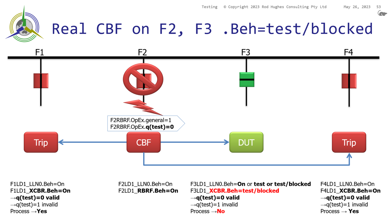
Send MMS command to set <<Fdr1_X_XCBR.Mod>> = 4 i.e <<.Mod>> = test-blocked so that the XCBR will not trip the CB when it receives any incoming signal with <<Fdr1_Pxxx.Op.q bit12>> = 1
It will still trip if <<Bus_X_PDIF.Op.stVal>> = 1 together with<<Bus_X_PDIF.Op.q bit12>> = 0 or <<FdrN_X_RBRF.OpEx.stVal>> = 1 together with <<FdrN_X_RBRF.OpEx.q bit12>> = 0
Now send similar MMS commands to the respective RREC Autoreclose LN and the RBRF LN depending on what you are attempting to test. You may also need to consider the intertrip scheme to the remote end via the PSCH Logical Node.
Finally you can now set the FUT LD/LN to <<.Mod>> = 3 as test to force the message to be sent with <<.q bit 12>> = 1
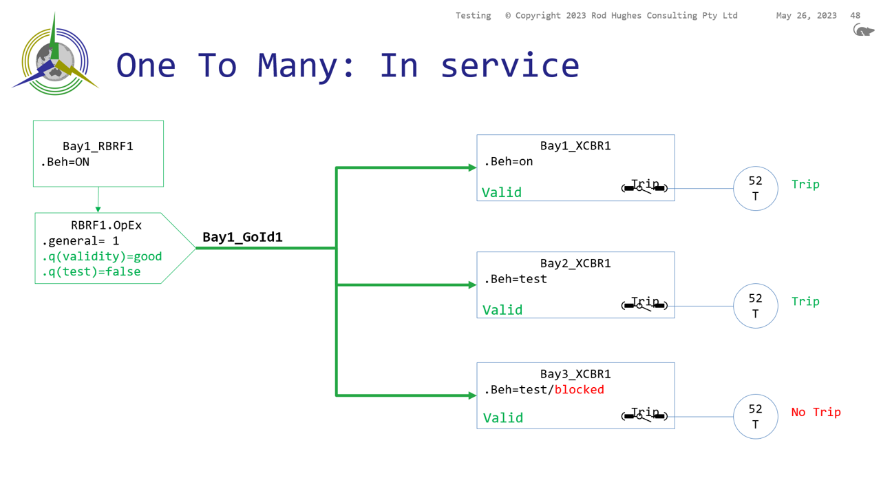
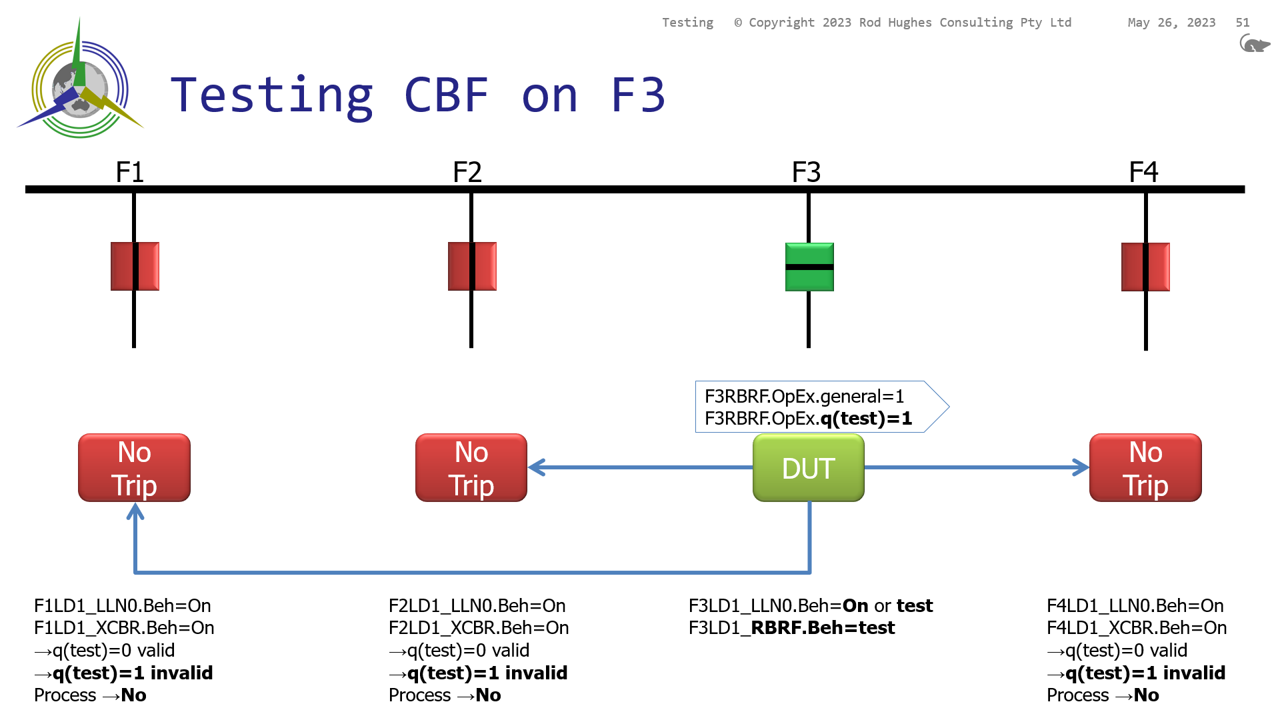
Scenario 1
As it is now, if I send command “Feeder1_XCBR.Mod=test” as Function Under Test (or one if its LD hierarchy Device Under test), it sits there with <<.Beh>>=test quite happily
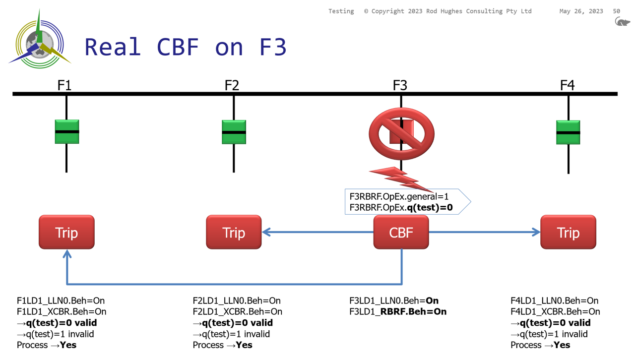
If a CB Fail event happens on Feeder 5, then that IED changes Feeeder5_RBRF.OpEx=1
When Feeder1_XCBR receives that changed GOOSE, it should STILL trip the CB because Validity=good, q(test)=false .. i.e. “processed as valid” causing a trip of Feeder 1.
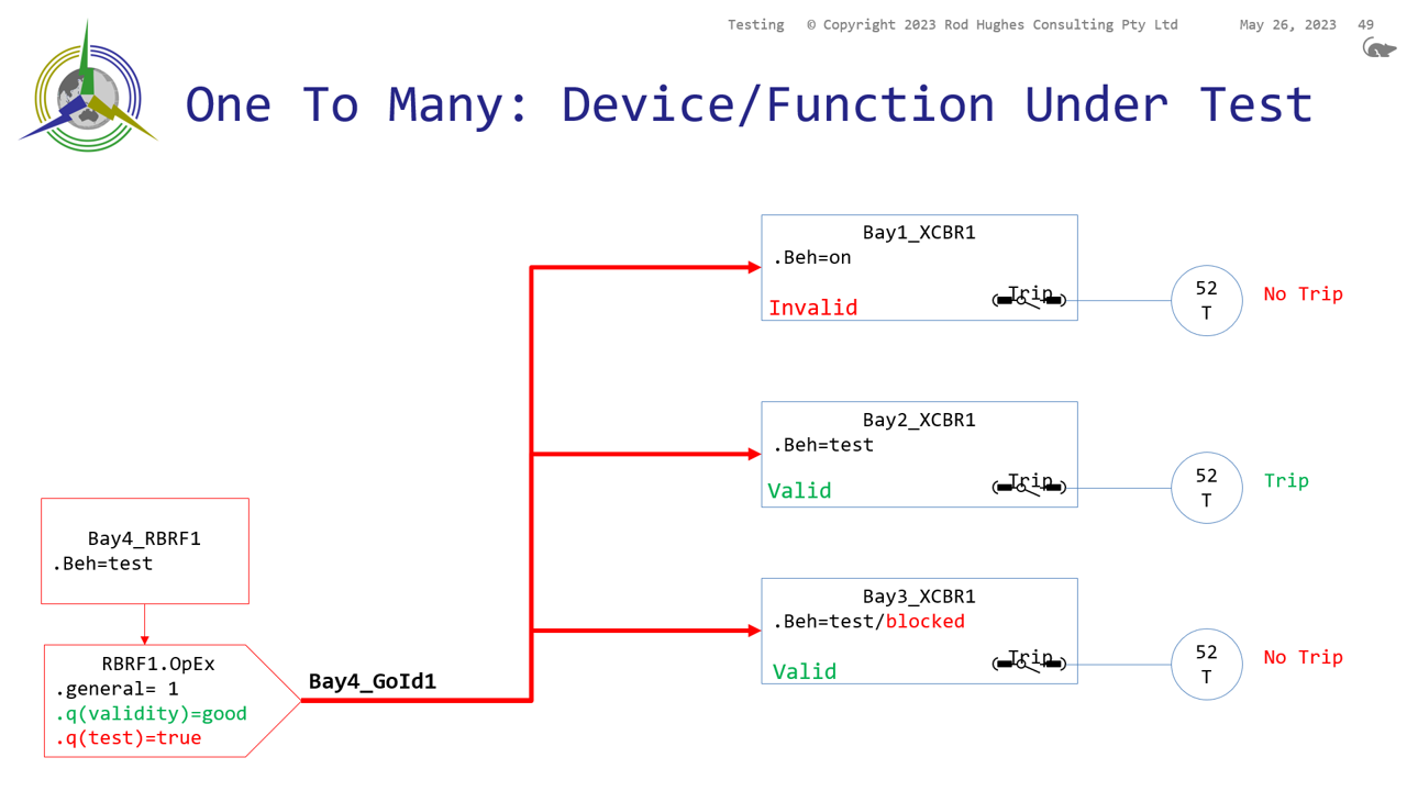
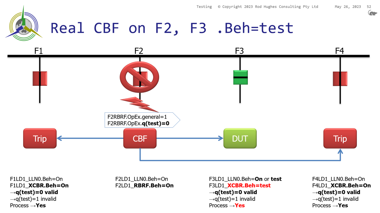
Scenario 2
In reverse when I am testing Feeder1_RBRF.. BECAUSE Feeder1_RBRF.OpEx.q(test)=true the OTHER feeders should ignore that ..
The other Feeders are still sitting with <<.Beh>>=on
So with their <<.Beh>>=on, their response to a message Validity=good, q(test)=true is to process as invalid .. i.e. ignore it and not trip.
These diagrams from my IEC 61850 training course Testing session may assist in understanding
- Protection Systems Engineering
- IEC 61850 Engineering
I provide a range of courses for company-specific in-house training and occasional public invitation courses. Contact me for details.
Contact Me
A phone call is nearly always welcome depending on the time of night wherever I am in the world.
Based in Adelaide UTC +9:30 hours e.g.
| April-September | Noon UK = 2030 Adelaide |
| October-March: | Noon UK = 2230 Adelaide |
Mobile + 61 419 845 253
Extra Notes:
Rod Hughes Consulting Pty Ltd accepts no direct nor consequential liability in any manner whatsoever to any party whosoever who may rely on or reference the information contained in these pages. Information contained in these pages is provided as general reference only without any specific relevance to any particular intended or actual reference to or use of this information. Any person or organisation making reference to or use of this information is at their sole responsibility under their own skill and judgement.
No Waiver, No Licence:
This page is protected by Copyright ©
Beyond referring to the web link of the material and whilst the information herein is accessible "via the web", Rod Hughes Consulting Pty Ltd grants no waiver of Copyright nor grants any licence to any extent to any party in relation to this information for use, copy, storing or redistribution of this material in any form in whole or in part without written consent of Rod Hughes Consulting Pty Ltd.