Power Factor - the facts
- Rodney Hughes
| Rod Hughes Consulting General Web Site | Applications Home | Innovations and Solutions Home | A bit about Rod Hughes |
|
|---|
Note - if the navigation pane on the left of this window is not visible, click the 2-pane icon on the top bar
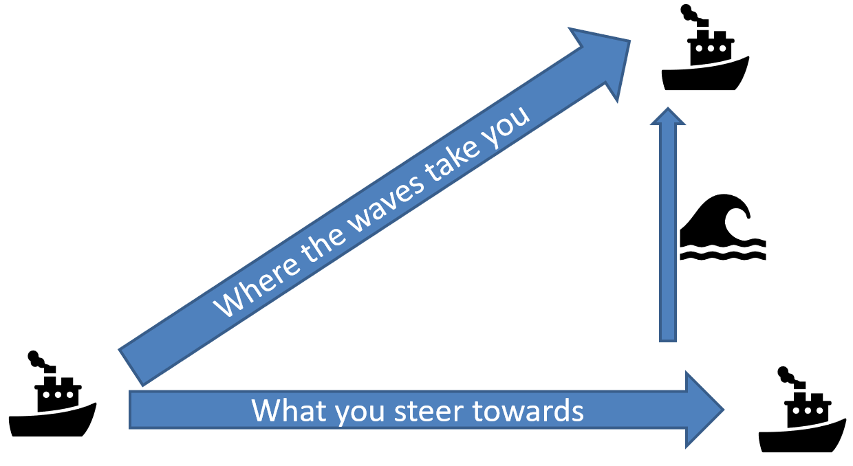
The concept of Reactive Power (var) is sometimes a bit abstract .. some have tried to explain it as the froth on a glass of beer but that is wrong as it is not a "linear" addition.
I suggest it is more like a powered boat heading off in one direction but the waves causing it to end up somewhere else - it is the combination of both the engine and the waves that gives the actual result of distance travelled.
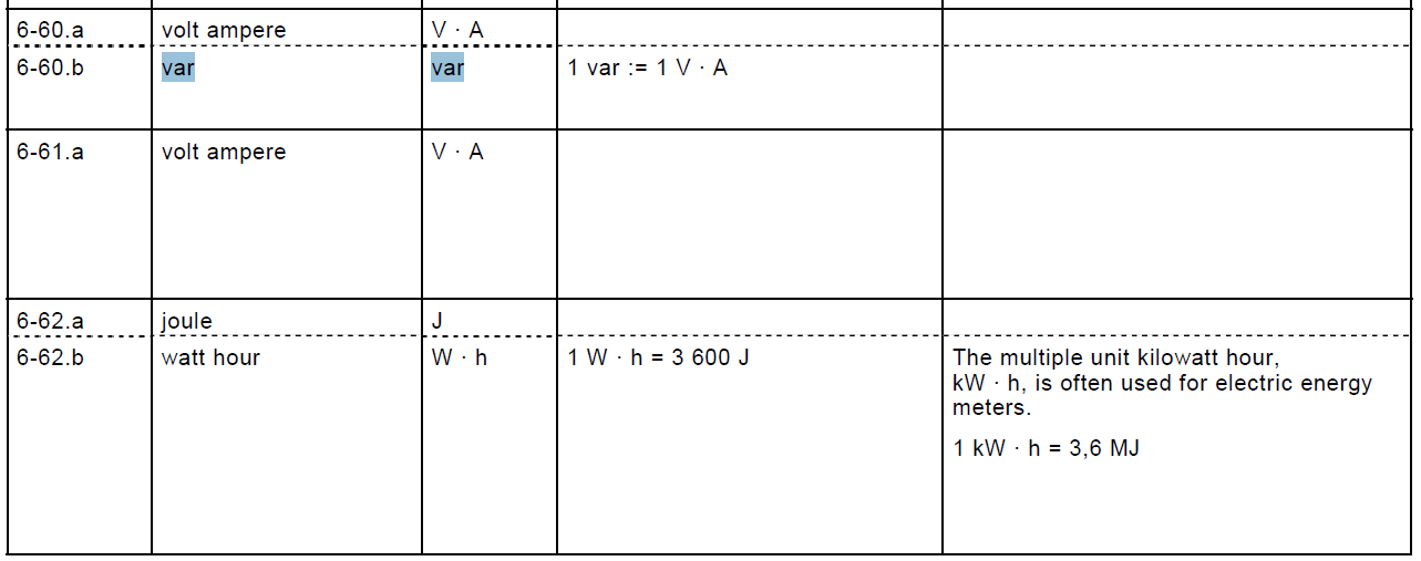
It is also worthwhile stating that there is no such thing as "VAR" or even "VAr"!
It is "var" .. all lower case!
Refer IEC 8000-6 .. noting the comparison to VA
That then leads us to the aspect of Power Factor
Power Factor seems to be a common and basic term in electrical engineering, but it suffers a lot of confusion about what it really means.
So let’s get back to basics to see the truth:
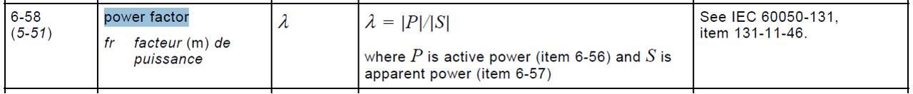
IEC Definition of Power Factor
IEC 8000-6 defines Power Factor as the ratio of the MAGNITUDE (absolute value) of Power (W) to the MAGNITUDE (absolute value) of apparent power (VA).
As such it can ONLY be a POSITIVE number
0 ≤ PF ≤ 1
Vector Analysis
General vector notation is a Magnitude and Angle with respect to some reference:
Magnitude at Angle <Phi degrees
Phi is the angle between one vector and another reference vector.
If we take the Voltage vector as the reference of zero degrees phase angle, then as an example we have a voltage of 100 volts referenced as:
Voltage vector = 100<0
Scenario 1 Unity Power Factor
If the load is purely Resistive as say 50 Ohms, the current will be exactly in phase with the voltage with magnitude of two amps in accordance with Ohm’s Law, then we have a current vector referenced as:
Current vector as 2<0
We can now define Apparent Power (some may call this Total Power) as S
S = voltage vector x current vector
Therefore S = (100<0) x (2<0)
Mathematics operations state that multiplying vectors, you multiple the magnitude and add the angle
S = (100 x 2)<(0 + 0) = 200<0
i.e. Apparent power = 200 VA in phase with the current vector (and voltage vector)

We also know that REAL Power (Watts) is the resistive axis quadrature component of the Apparent Power, which is obviously perfectly in phase with the S vector, which is perfectly in phase with the Current vector which is perfectly in phase with the voltage vector, i.e. since current is in phase with the volts, Phi = 0
P = S x cos(Phi) = 200 x cos (0) = 200 x 1.0 = 200 Watts
We can now calculate Power Factor as
Power Factor = Magnitude of REAL Power / Magnitude of APPARENT Power
PF = 200/200 = 1.0
We can also see that since:
Real Power = Apparent Power x cos(Theta)
Theta = angle between P and S
then we can also calculate Power Factor as:
Power Factor = cos(Theta) = cos (0) = 1.0
Scenario 2 Power Factor of an Inductive Load
To note that there are two definitions of S in IEEE 1459: 2010
Clause 3.1.1.4 Apparent Power S = VI
Clause 3.1.1.6: Complex Power S = VI*
where I* is the complex conjugate of I
So for I = |Im| @ -Θ
I* = |Im| @ +Θ
The reason we need to use I* is that just using I results in the S vector moving around the P:Q plane depending on the angle of the reference vector and whether I is with respect to V, or V is with respect to I.
However the net effect of that is that Q is positive for an inductive load.
This is fully described in /wiki/spaces/AP/pages/78479362
As an example, in the spreadsheet attached to that page, setting the reference vector to say 60° but with a pure resistive load results in Apparent Power S appearing at the angle of the reference vector .. when clearly Q should be zero and the S should lie on the east/west axis for power. Complex Power however remains in its correct Quadrant for the relationship between V and I.
For simplicity the following discussion on this page (erroneously) uses Apparent Power simply because when Voltage is the reference vector at angle zero, the angle of the Apparent Power S happens to be at the same angle as the current so visually it is easier to follow. In reality Complex Power would flip the triangle upside down compared to the following diagrams.
If the load is partially inductive – say a motor, still required to do 200 Watts of Real Power component to drive its load, but it also has an inductive impedance component (therefore current lags voltage) equivalent to 40 var

Apparent Power S = 200 – j40 = 203.96 VA at an angle of -11.31 degrees
Considering Trigonometry , Power Factor is the ratio of the length of the base divided by the length of the Hypotenuse.
We can now calculate Power Factor as
Power Factor = REAL Power / APPARENT Power
Power Factor = 200/203.96 = 0.98
Another way of understanding what Power Factor means is as a percentage indicating energy conversion efficiency.
In this example, Power Factor = 0.98 means that 98% of the total Apparent Power (S), i.e. supplied energy, is converted to REAL Power (P).
We can also see that since
Real Power = Apparent Power x cos(Theta)
Theta = angle between P and S
We can also calculate Power Factor as
Power Factor = cos(Theta) = cos (-11.31) = 0.98
This increase in Apparent power in order to supply the same REAL Power is the reason we try to bring PF as close as possible to unity. Generating vars is a waste of energy compared to using just enough to do the real work in Watts.
If you are billed in peak W Demand and/or Wh Consumption, any change in Power Factor between Scenario 1 and Scenario 2 will not change your energy bill since the REAL Power is the same in both scenarios.
However, if you are billed in peak VA Demand and/or VAh Consumption, the reduction in Power Factor as a result of the increase in Apparent Power will cost you at least an extra 2% on your electricity bill. It may be more than just the 2% as it reflects not only the cost of the fuel to produce the Apparent Power, but also the size of the generators, wires and transformers being the electricity infrastructure necessary to cope with that higher amount of Apparent Power.
In some cases, another way to calculate Power Factor other than the ratio of P (Watts) to S (VA) is to consider the Voltage and Current Vectors themselves.
Since the Voltage vector is still the reference vector, the Current and the Apparent Power vector are in phase so we have
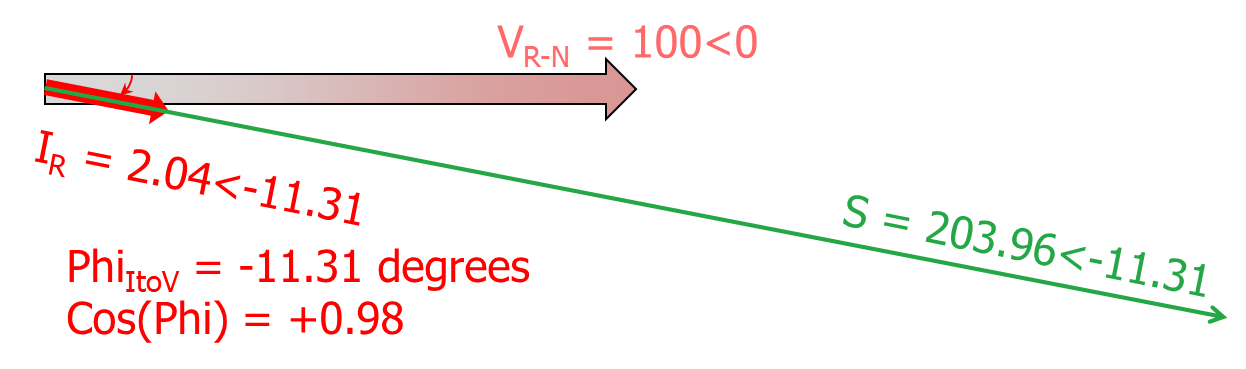
So in this case, Cos(Theta) = Cos(Phi) = +0.98
Scenario 3 Adding Capacitance To An Inductive Load
We now decide to add 70 var of capacitance to the load with the motor still doing the same workload, i.e. the REAL Power is the same 200 Watts, but in addition to the 40 var of motor inductance, there is 70 var of capacitance
So the total var is now -40 + 70 = +30 var i.e. total reactive power is now 30 @+90°
S' = S + 70<90
S' = 200 -j40 + j70= 200 +j30
S' = 202.24<+8.53


Power Factor = REAL Power / APPARENT Power = cos(Theta)
PF = 200/202.24 = Cos(8.53) = +0.99
The voltage vector is still 100@0°
Since the Apparent Power Vector must be in phase with the Current Vector, the current vector must now be at an angle of +8.53°

So again we can also use the simplification of
cos(Phi) = +0.99
Unfortunately some people get confused with the change in vars direction of adding 70 var to an existing -40 var load changes the overall sign of the total vars from negative to positive, that therefore the Power Factor has also changed sign – that is clearly NOT true.
We can also therefore deduce that as a ratio of the two magnitudes always being positive, and that Cos(Theta) with Theta always in the range -90<Phi<+90 by definition of quadrature components, the possible range of Power Factor will be from 0 to +1.0!
Note: REGARDLESS of the amount of vars, and REGARDLESS of forward or reverse Real Power flow, Power Factor is ALWAYS POSITIVE.
Power Factor can NEVER be Negative.
Hence we must always refer to the Power Factor as Unity or as Capacitive Leading or Inductive Lagging.
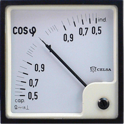
Note these metres simply have V and I connected to them and those inputs provide flux interactions to the armature, i.e. they do not calculate S and P. Hence these meters are correctly showing "cosφ" i.e. cos(Phi), with Phi as the angle between V and I.
The key aspect though is that they do NOT show negative values!
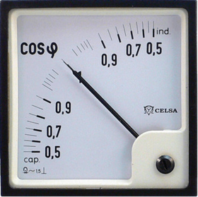
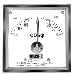
Note that for the same inductive load, the meter on the left would swing its pointer to the RIGHT, whilst the right hand meter would swing its pointer to the LEFT. (i.e. if you were wrongly assigning +/- as capacitive/inductive, for the meter on the left would have "+" below the unity value, whilst on the meter on the right would have + on the right-hand side of unity!) ... so read the small print on the meter as which side of unity means what!!!
That is where some confusion comes in when quoting what the Power Factor is, is that on the basis that Power Factor by such calculations is always positive, in order to distinguish whether the load is operating as lagging or leading, it might seem reasonable to "throw in" a "+" or a "-" sign to indicate Leading or Lagging.
Well, so it would seem … but ...
First note that both meters show Power Factor as only POSITIVE values either side of 1 as unity Power Factor, i.e. they both start at a low of 0.5 (positive), increase to 1.0, then decrease back to 0.5 (also positive).
That makes a lot of sense as it would be odd for a scale to jump as it goes through unity from -0.8 to -0.9 to 1.0 to +0.9 .. and then what is the right way to show unity Power Factor .. as +1.0 or -1.0??
Imagine a load of 200 W Real Power and -40 var inductive and slowly adding capacitance from 0 at 10 var at a time:
With the same 200 W Real Power, it starts at total var = -40 then PF = +0.981
-40 var at -11.31 deg then PF= +0.981
-30 var at -8.53 deg then PF = +0.989
-20 var at -5.71 deg then PF = +0.995
-10 var at -2.86 deg then PF = +0.999
0 var at 0.00 deg then PF = +1.000
10 var at +2.86 deg then PF = +0.999
20 var at +5.71 deg then PF = +0.995
30 var at +8.53 deg then PF = +0.989
40 var at +11.31 deg then PF = +0.981
If we now look at a Power Factor Meter

If we now look at the scale of the Power Factor meter as a flat line as a full scale from -1 to 0 to +1 and then indicate where the pointer is for the different values of inductive or capacitive load
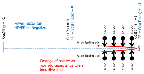
They are ALL showing POSITIVE Power Factor.
That is the nature of Trigonometry to determine PF.
Values change sign from negative to positive (or vice versa) when they pass through zero.
They do not change sign when they slowly increase towards a value of 1 and then start to decrease from 1. The Power Factor NEVER passes THROUGH zero by simply adding or subtracting capacitance - it will only have the range
0 < Power Factor < =1 whilst ever power flow is positive i.e TO the load.
Which then raises the obvious question: Can Power Factor really be NEGATIVE in the power system?
Scenario 4 Reverse Power Flow FROM The Load
When we look at the four quadrants of the vector diagram, what if the current lags or leads the voltage by MORE than 90 degrees? Can Power Factor be NEGATIVE?
That cannot happen just by adding more inductance or more capacitance – that just changes the vars component but does not reverse the Watts component to be in the left side of the diagram as we have shown above.
Quite simply if the current lags or leads the voltage by more than 90 degrees, that means the direction of power flow is back towards the normal source for generation, i.e. the load has itself become a generator – perhaps it is a motor now operating on regeneration from a high inertia load, or perhaps it is just a consumer’s renewable energy solar PV generating back to the grid.

Power Factor = ratio of magnitudes of REAL Power / APPARENT Power = 200/ 203.96 = +0.98
Note that as a ratio of magnitudes, Power Factor is still POSITIVE
Power Factor = cos(Theta) = cos(11.31) = +0.98
Note that as a Cos of the angle between P and S, Power Factor is still POSITIVE
However if we are basing the calculation of Power Factor on measuring the angle Phi between the Voltage Vector and the Current Vector, then
Power Factor = Apparent Power x cos(Phi) = 200 x cos(-168.46) = -0.98
This "pseudo" measure of Power Factor calculated by Cos(Phi) being the angle between Volts and Amps can now be in the range -1.0 to +1.0 .... it would seem that Power Factor can be NEGATIVE ...
However it is called "Power Factor" - it is not called "Volts to Amps Factor"
Technically Power Factor is ONLY allowed to be positive between 0 and +1.0 according to the definition as the ratio of magnitudes regardless of power flowing to or away from the load.
A negative Power Factor is technically wrong according to the definition as the ratio of magnitudes regardless of power flowing to or away from the load.
However using the angle between voltage and current directly gives us more information as to the direction of power flow to or from the load based on being POSITIVE or NEGATIVE. This negative result for the "pseudo Power Factor" can be the case in a simple analogue panel meter if it is fully scaled -1 to + 1 indication using interactions of the flux generated by a voltage input and a current input, or in the case of a numeric “Intelligent Electronic Device” just using the phase angle measured between the current and voltage sampled waveform.
Scenario 5 Effect Of Incorrect CT Polarity
If the Power Factor is showing as Negative, instead of reverse power flow as Scenario 4, it could alternatively be that the CT polarity for measuring the primary current is in the wrong polarity: e.g. in the above original example of just the motor where the current lags the voltage by 11.31 degrees, a reverse CT polarity would mean the current is seen to be LEADING the voltage by 168.69 degrees.

With the convention that lagging angles mean inductance, it would APPEAR according to the CT secondary current, that the inductive load has become capacitive.
If a Power Factor Correction system is in use, and depending on how it determines the overall var component, the controller would decide to reduce the amount of capacitance on the system. This would make the primary power factor worse without that compensation capacitance, i.e. it would move more inductive. This would result in the CT secondary current showing the power factor as yet lower value of LEADING power factor (even more capacitive) and hence the controller would try to remove more capacitance. This ends up as a runaway situation where all controllable capacitance is removed from the system, leaving the original non-compensated inductive lagging power factor with a lot of wasted energy, and higher cost electricity bills.
So in general, a properly installed CT with correct polarities connected to a device for displaying Power Factor should only show positive Power Factor.
If it is showing negative Power Factor, it means it is using the simplified Cos(Phi) calculation rather than ratio of magnitudes - but don't allow yourself to get confused that negative means inductive whilst positive means capacitive - that interpretation is 100% wrong.
Scenario 6 Effect Of Incorrect Voltage Connection
There is another way in which Power Factor can be displayed incorrectly apart from incorrect CT polarity. Clearly Power Factor implies a phase relationship between voltage and current, and hence even if the current vector is in the right polarity, presenting the indicating device with the incorrect voltage will yield an incorrect result.
In the above examples, we have defined unity PF as being when the current vector IR is in perfect phase with the Phase-to-Neutral Voltage VR-N.
However suppose the instrument is inadvertently connected to the VY-N or the VB-N voltage instead?
Consequently if we take Scenario 2, but incorrectly connect the VB-N vector we have these quantities being measured:
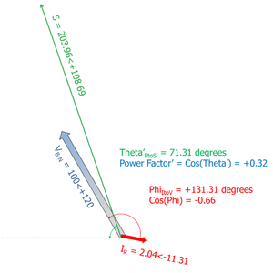
The interesting thing here is that the angle between the VB-N and the IR is +131.31 degrees
So it would seem that the pseudo Power Factor measured on the basis of connecting these quantities to our Power Factor instrument which uses the angle between the V and I vector would be:
Cos(Phi) = Cos(+131.31) = -0.66
We could therefore expect that a cos(φ) meter working on the basis of measuring the phase angle between V and I would yield a pseudo Power Factor = -0.66
However even Phi is NOT the Theta of the Power Factor triangle created from the incorrect voltage connection.
As we can see, because of the vector shift, the Apparent Power is a value of 203.96 VA at an angle Theta of 108.69 degrees
S = 203.96<+108.69
Therefore
P = -65.36 Watt
Q = +193.31 var
Therefore actual Power Factor created as a result of the incorrect voltage connection as defined by Cos(Theta) of the Power triangle is
Power Factor = P/S = Cos(Theta) = Cos(108.69) = -0.32
Obviously both are still wrong compared to the real power system Power Factor of +0.98
It is further to note that if indeed the load becomes MORE inductive, e.g. Ir goes to say an angle of 35 degrees, the S vector would now swing back into the top right quadrant at an angle of +85 degrees and hence the false Power Factor reading would change to POSITIVE +0.09 despite the phase angle between V and I now being 155 degrees and therefore Cos(Phi) by that method being negative at -0.91 !!
Note some Power Factor Meters are connected with Phase-to-Phase voltage instead of Phase-to-Neutral, e.g. VR-Y and IR, or more commonly in quadrature as VY-B and IR. The analysis is the much the same. You just have to consider whether you are looking at a "V vs I" phase angle or the "P vs S" ratio.
Conclusion - Power Factor is a measure of efficiency in the range 0 to +1
So where does all that leave is?
Power actor means how much of the total Apparent Power (S VA) is converted to Real Power (P Watts).
Power Factor is therefore a measure of energy efficiency of the power load configuration.
As such Power Factor can ONLY be POSITIVE i.e. in the range 0 < Power Factor < +1
Negative efficiency does not exist!
It can be highly inefficient near zero, or highly efficient near 1.
The intervening values simply indicate a waste of energy of reactive power (capacitive or inductive).
Power Factor does NOT indicate whether the reactive Power is due to inductive or capacitive components in the load, just that it is there in one form or the other.
If you do have a negative Power Factor indication, either the CT is in the wrong polarity, or the voltage source is not the right combination for that device, or it is really a pseudo measurement device of the phase angle between Voltage-and-Current expressed as a cosine value and therefore power flow is in the reverse direction to the defined forward direction (it might be better to just display that result in degrees!)
Some electronic meter devices confuse the matter even further.
e.g. without naming the meter, one electronic meter at least defines how it handles Power Factor as:
The ***** Phase Angle & Power Factor Meter computes power factor as cos(θ) from phase angle θ. Power factor readings can range from 1.000 to 0.000 with three decimal places and an accuracy of 0.1% for sinusoidal signals at 50/60 Hz power line frequency. While power factor is always positive, the meter artificially assigns a minus sign to power factor for negative phase angles, and it sets power factor to 0 for phase angles greater than 90°.
This meter is in contradiction to Alex McEachern's paper (http://powerstandards.com/Shymanski/draft.pdf) with regard to what negative PF means (if indeed you agree with Alex McEachern’s paper that negative PF can exist).
So this meter supplier has added their own proprietary interpretation on their display and added another “proprietary” convention for angles >90!!
Now go put that meter on a feeder in the middle of the grid with bi-directional power flow!!! What happens when power flow reverses??? PF goes to zero!!!!
Or indeed put one meter at one end of the line and another at the other end of the line with the common policy that power flow is defined as positive away from the busbar, one reads a value, the other zero!.
What this supplier perhaps should do is instead of displaying a minus sign for lagging and a zero for >90°, put the letter L for lagging or C for leading, or some such defining character.
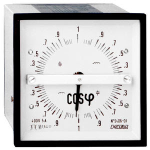
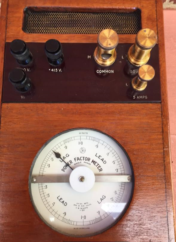
Here are a few typical PF meters. Note that none of them show PF as negative - even the full 360° meters.
They do indicate Lead/Lag or Cap/Ind.


Bottom line ....
Now I know that colloquial terminology often uses some form of "short hand" to infer a certain combination of pieces of information.
But whilst some might use a negative PF to indicate inductive load, others would argue that it simply means Real Power is in the reverse direction - these two assumptions are 90 degrees apart.
Which one is right, ... or because they in themselves do not give you the complete answer (so much for the shorthand) are they both a poor use of impossible terminology? I would contend the latter and to consider a negative Power Factor as simply invalid .. at least till you find out what the intended meaning is!
So if you have a Power Factor of less than 1, that value alone does not tell you whether to add or remove capacitance to fix a reactive load.
If you also know that it is less than 1 AND it is Inductive Lagging, then you know you need to add capacitance to the load or reduce the inductance of the load
If you also know that it is less than 1 AND it is Capacitive Leading, then you know you need to remove capacitance from the load or increase the inductance of the load
.... But if you have a negative Power Factor, you need to find out what is the meaning of the minus sign as applied by the context of the device vendor, and also check your CT and VT polarities.
Interactive Model
This spreadsheet models selection of the four quadrants and provides full numerical and graphical representation.
Down load the spreadsheet, then in the yellow highlighted cell (all other cells are locked) just change the number of the Quadrant you wish to see (1 - 4).
Copy this permanent link to this page: https://rhconsult.tiny.us/34pb7drz
- Protection Systems Engineering
- IEC 61850 Engineering
I provide a range of courses for company-specific in-house training and occasional public invitation courses. Contact me for details.
Contact Me
A phone call is nearly always welcome depending on the time of night wherever I am in the world.
Based in Adelaide UTC +9:30 hours e.g.
| April-September | Noon UK = 2030 Adelaide |
| October-March: | Noon UK = 2230 Adelaide |
Mobile + 61 419 845 253
Extra Notes:
No Waiver, No Licence:
Rod Hughes Consulting Pty Ltd accepts no direct nor consequential liability in any manner whatsoever to any party whosoever who may rely on or reference the information contained in these pages. Information contained in these pages is provided as general reference only without any specific relevance to any particular intended or actual reference to or use of this information. Any person or organisation making reference to or use of this information is at their sole responsibility under their own skill and judgement.
This page is protected by Copyright ©
Beyond referring to the web link of the material and whilst the information herein is accessible "via the web", Rod Hughes Consulting Pty Ltd grants no waiver of Copyright nor grants any licence to any extent to any party in relation to this information for use, copy, storing or redistribution of this material in any form in whole or in part without written consent of Rod Hughes Consulting Pty Ltd.