Power Factor Correction
| Rod Hughes Consulting General Web Site | Applications Home | Innovations and Solutions Home | A bit about Rod Hughes |
|
|---|
Note - if the navigation pane on the left of this window is not visible, click the 2-pane icon on the top bar
Power Factor Correction is a means of reducing the overall current needed to supply a particular load - that means less I2R losses to the load, potentially smaller cables, smaller transformers and smaller rating switchgear (or perhaps avoiding the need for larger ones).
In some cases utilities charge for the maximum MVA demand of the load so improved Power Factor closer to unity keeps the total kVA demand as low as possible, and hence lower electricity bills.
e.g. Consider a 22 kV system with a load that is drawing 1000 A at a Power Factor of 0.95 Lagging (i.e. it is an inductive load).
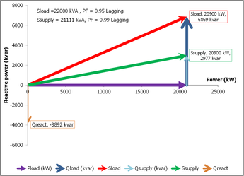
This represents an overall Apparent Power = 22 MVA load comprising 20.90 MW of Real Power (P) plus 6.87 Mvar of "wasted" Reactive Power (Q).
If we improve the Power Factor to 0.99 lagging by adding some capacitor banks in parallel to the load, we still have the same Real Power 20.9 MW but the total Reactive Power has been reduced to 2.98 Mvar.
The total Apparent Power is now only 21.11 MVA and the total current drawn from the supply is reduced to 959.6 A
To achieve this improvement, some 25.6 uF of capacitance is needed to achieve this 4% reduction.
It is to note that the load itself is still 22 MVA at 0.95 Lagging, it is just the total supply to the combined load and capacitor banks that has changed.
If we wanted to achieve total unity Power Factor, we would achieve total demand as 20.9 MVA and just 950 A, i.e. total 5% reduction, but we would need total 45.18 uF of capacitance i.e. to achieve that extra 1% reduction we need to almost double the amount of capacitance we have added - the "law of diminishing returns".
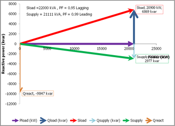
Note that it is possible to over-correct from 0.95 lagging to 0.99 leading by adding 64.7 uF as too much capacitance - it achieves the same 21.11 MVA total Apparent Power but at the expense of additional capacitance so it is generally wise to remain slightly less than unity Power Factor.
You can enter your own system details in the attached spreadsheet model.
Copy this permanent link to this page https://rhconsult.tiny.us/yckvjxuw
- Protection Systems Engineering
- IEC 61850 Engineering
I provide a range of courses for company-specific in-house training and occasional public invitation courses. Contact me for details.
Contact Me
A phone call is nearly always welcome depending on the time of night wherever I am in the world.
Based in Adelaide UTC +9:30 hours e.g.
| April-September | Noon UK = 2030 Adelaide |
| October-March: | Noon UK = 2230 Adelaide |
Mobile + 61 419 845 253
Extra Notes:
No Waiver, No Licence:
Rod Hughes Consulting Pty Ltd accepts no direct nor consequential liability in any manner whatsoever to any party whosoever who may rely on or reference the information contained in these pages. Information contained in these pages is provided as general reference only without any specific relevance to any particular intended or actual reference to or use of this information. Any person or organisation making reference to or use of this information is at their sole responsibility under their own skill and judgement.
This page is protected by Copyright ©
Beyond referring to the web link of the material and whilst the information herein is accessible "via the web", Rod Hughes Consulting Pty Ltd grants no waiver of Copyright nor grants any licence to any extent to any party in relation to this information for use, copy, storing or redistribution of this material in any form in whole or in part without written consent of Rod Hughes Consulting Pty Ltd.


