How do Zig-Zag Earthing Transformers work?
- Rodney Hughes
| Rod Hughes Consulting General Web Site | Applications Home | Innovations and Solutions Home | A bit about Rod Hughes |
|
|---|
Note - if the navigation pane on the left of this window is not visible, click the 2-pane icon on the top bar
Earthing of power systems is an important consideration for both safe step-and-touch and maximum fault level considerations. There are however specifically "isolated networks" where the system is "non-effectively earthed" based on a Petersen Coil principle which is somewhat based on a Neutral Grounding Reactor approach, but that is not the focus of this page.
Star windings are easily earthed as typically done in the following four options at the neutral star point of the three windings.
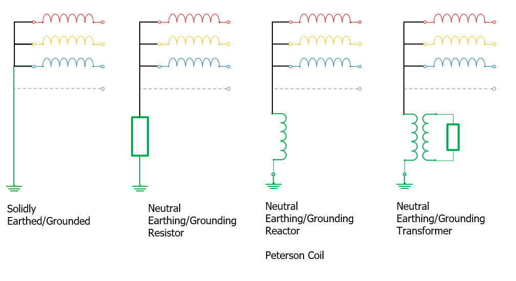
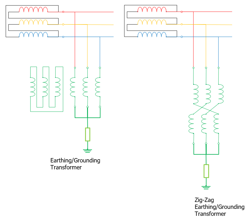
However delta connected systems do not have any "neutral" point as the star point of the three phases. Hence a different earthing method is required as either a star/delta earthing transformer or a special "cross connected" transformer known as a Zig Zag Earthing Transformer.
The first is reasonably straight forward as the delta winding forces the condition that only zero sequence currents can flow.
The Zig-Zag also only allows zero sequence currents to flow but at first is not quite so obvious as to how.
Zig Zag Earthing Transformer Operation
At the outset allow me to state clearly:
For Zero Sequence currents, the Zig-Zag windings are effectively zero impedance - fault current is limited purely by the main transformer impedance, the line impedance to the fault, the impedance of the fault, the return ground impedance and any earthing impedance in the earth leg from the zig-zag to earth.
For Positive or Negative Phase Sequence, the Zig-Zag windings are effectively infinite impedance.
Some explanations of Zig-Zag Earthing Transformers (ZZET) jump straight in to sequence component diagrams and calculations of Positive, Negative and Zero Sequence impedances.
A useful reference paper on ZZET was written by Anna Guldbrand of Lund University in 2006: "Central or Local Compensation of Earth-Fault Currents in Non-Effectively Earthed Distribution Systems"
I prefer to explain ZZET by simply considering where current can flow using the "age-old" and very simple "follow the arrow" technique ![]()
These types of transformers look complicated, but in reality are just applying the law of Ampere.Turns balance across two windings on the same limb, i.e. if current is flowing in one winding, current must be flowing in the other.
The trick is in the means of connecting the principal six windings (some ZZET have 12 windings in total - refer section on Combined ZZET and Auxiliary TF).
The non-polarity end of the A-phase top winding is connected to the non-polarity end of the B phase bottom winding.
The non-polarity end of the B-phase top winding is connected to the non-polarity end of the C phase bottom winding.
The non-polarity end of the C-phase top winding is connected to the non-polarity end of the A phase bottom winding.
The cross connection of the windings on different limbs creates current flow dependencies which only apply if the currents in all windings are in phase ... i.e. the currents are Zero Sequence currents and hence are the physical reality of a earth fault.
| Current flowing up from the neutral (purple) to the polarity end of A phase bottom winding will therefore flow up and through the top winding of C-phase and onto the grid (Figure 1). |
Figure 1 |
As C-phase top has current flow, there must be corresponding current flow in C-phase bottom (orange) (Figure 2) Since the two C-phase windings are on the same limb, they shar the same flux in magnitude and angle. Hence the purple and orange currents on the C-phase limb windings must be in-phase and same magnitude. |
Figure 2 |
Therefore there must be current flow (orange) in from the earth and out on B phase to the grid (Figure 3): |
Figure 3 |
As B-phase top has current flow, there must be corresponding current flow in B-phase bottom (green) (Figure 4) Since the two B-phase windings are on the same limb, they shar the same flux in magnitude and angle. Hence the orange and green currents on the C-phase limb windings must be in-phase and same magnitude. |
Figure 4 |
Therefore there must be current flow (green) in from the earth and out on A phase to the grid (Figure 5): Since the two A-phase windings are on the same limb, they shar the same flux in magnitude and angle. Hence the green and purple currents on the C-phase limb windings must be in-phase and same magnitude. |
Figure 5 |
")
")
")
")
")
It is to note that all currents in each set of top or bottom windings as well as the earth connection are IN-PHASE.
Purple is in phase with green which is in phase with orange!
They must therefore be real ZERO SEQUENCE currents Ia-0, Ib-0, Ic-0, the sum of which is the total earth fault current Ia-0 + Ib-0 + Ic-0 = If.
Note that Positive Sequence and Negative Sequence 3-phase currents cannot flow through the ZZET because the currents are not in phase. Hence the ZZET presents itself as an open circuit for
It is also to note that as shown in Figure 6, if any one phase is not connected to the grid, e.g. a single fuse blows (unlikely) or a connection has not been made, the earthing transformer winding dependencies cannot work and there is no earth fault current able to flow. The open circuit of one phase (Figure 6 C-phase grid connection is not connected) means there cannot be corresponding current flow in its bottom winding, and the corresponding flow on to the windings on the other cores. |
Figure 6 |
")
It is therefore critical that Earthing Transformers are solidly connected to the earth and to the grid. It is therefore somewhat inconsistent to provide mechanical switching of Earthing Transformers In/Out of service via switchgear.
Earth Fault Detection with Earthing Transformers
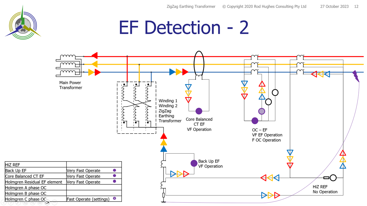
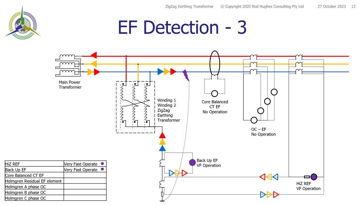
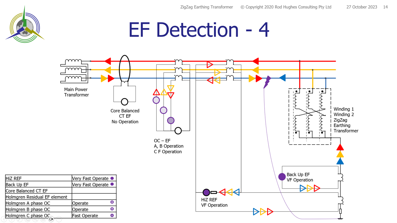
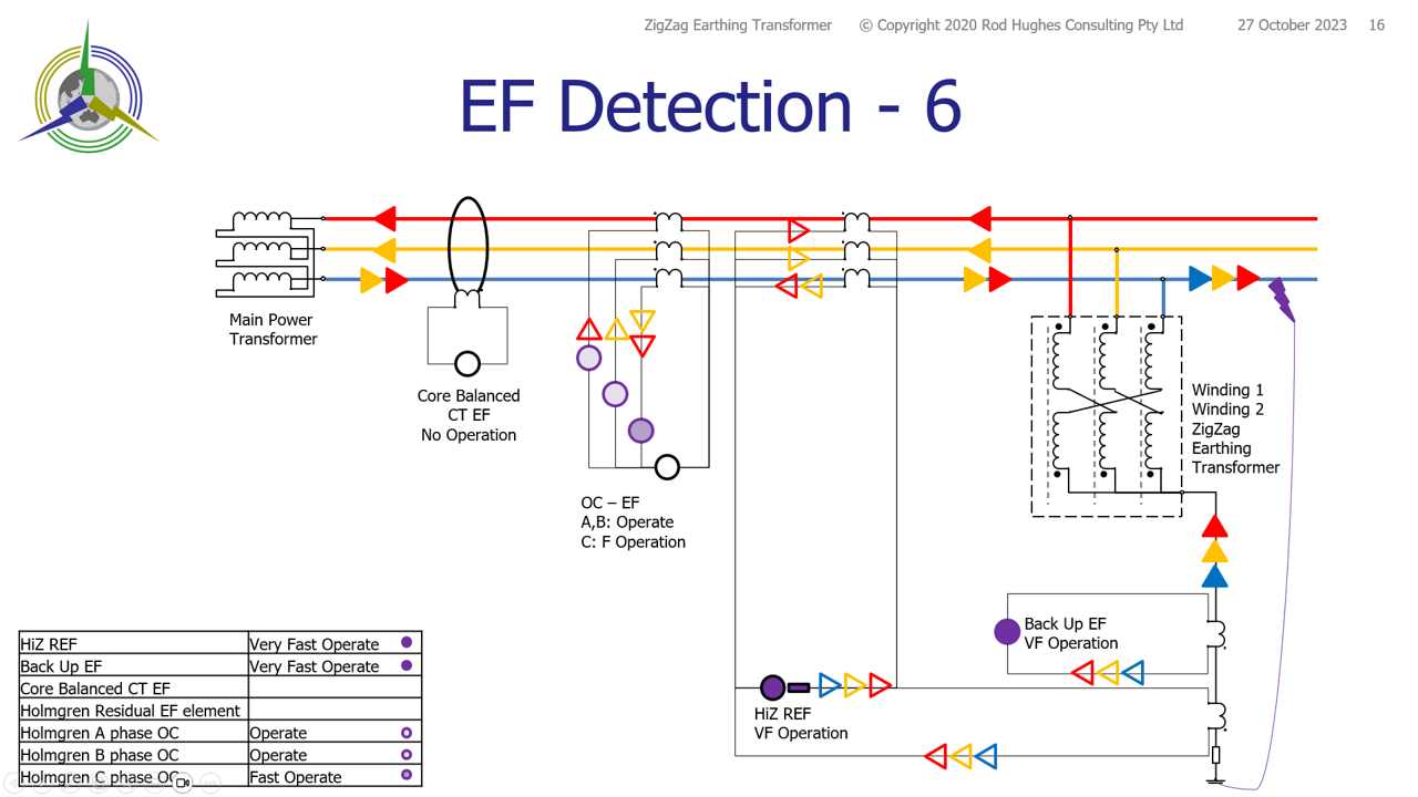
There are three earth fault scenarios for each consideration of where the ZZET is located with respect to the line CTs:
- ZZET to left of main CTS
- EF between TF and Earthing Transformer
- EF beyond the Restricted Earth fault line CTs
- EF between the Earthing Transformer the Restricted Earth fault line CTs
- ZZET to right of main CTs
- EF between ZZET and line CTs
- EF between line CTs and main transformer
- EF to the right of ZZET
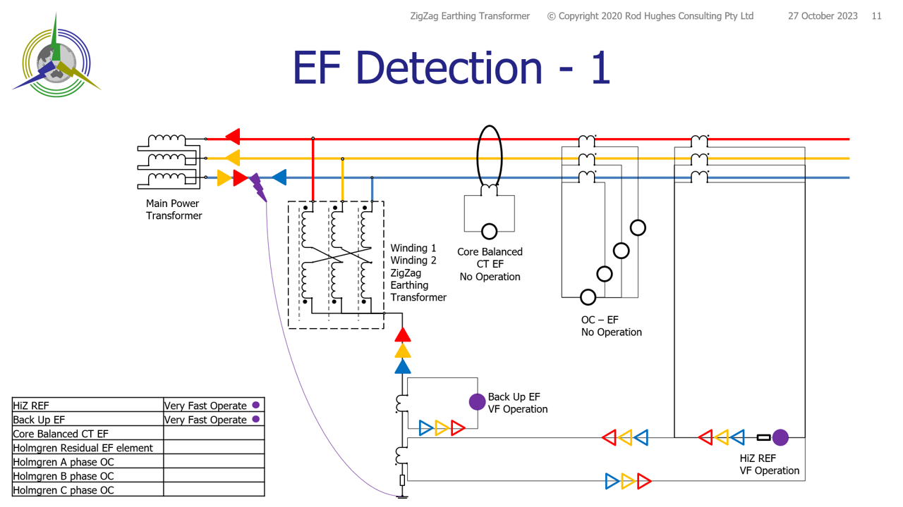 Figure 7 |
Figure 8 |
Figure 9 |
Figure 10 | 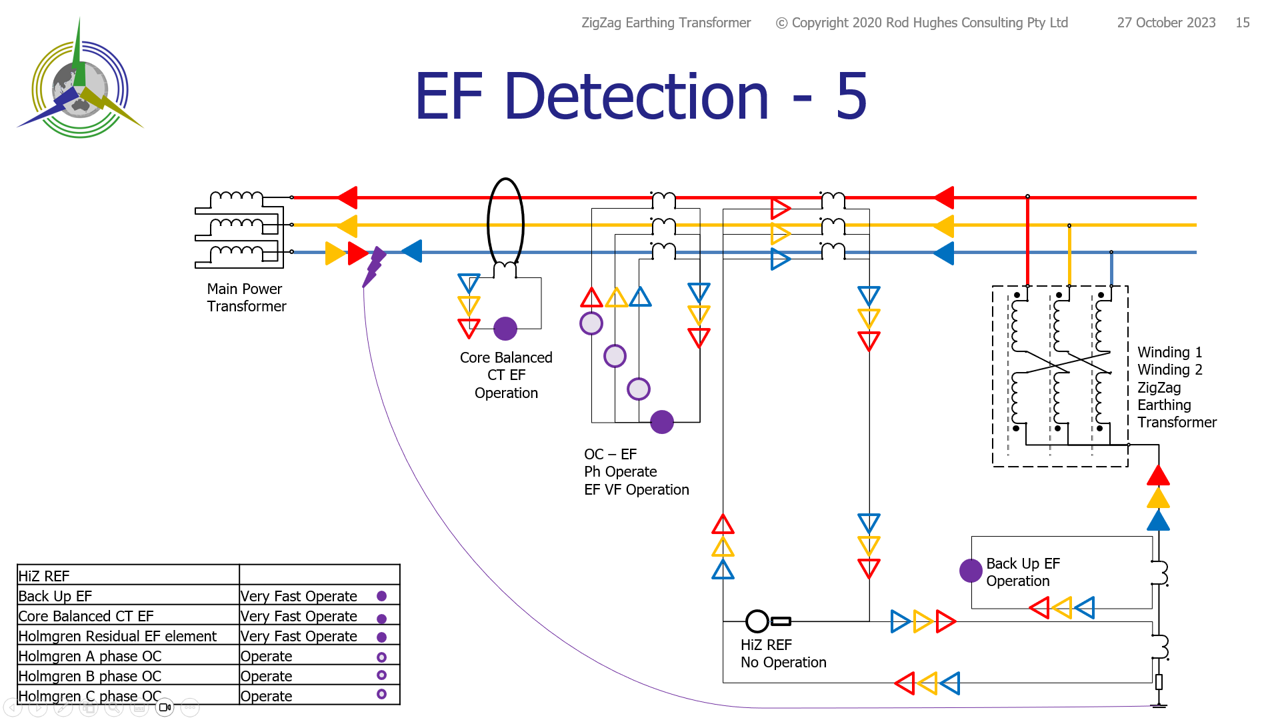 Figure 11 |
Figure 12 |
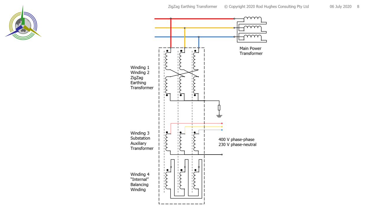
Combined Earthing Transformer and Auxiliary Transformer
The Earthing Transformer is essentially a voltage transformer with special connections.
There is also a requirement to provide a station auxiliary supply which usually requires an Auxiliary Transformer associated with the Power transformer.
The substation footprint size therefore must cater for the Power Transformer, the Earthing Transformer and the Auxiliary Transformer
However in addition to the zig-zag windings, the same limbs can be used to provide a third winding as the station low voltage 400 V 3-phase, 240 V 1-phase supply. This eliminates the need for a separate auxiliary transformer, saving substation land cost (equipment footprint) and equipment cost. However this extra winding #3 must be balanced with a fourth winding to ensure ampere.turns balance on each limb is achieved. |
Figure 13 |
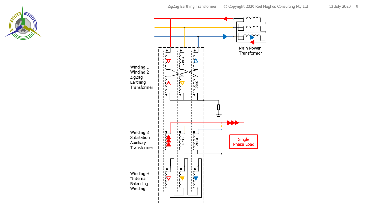
This can be seen considering a phase load connected to one station auxiliary phase. If the load creates 3 units of current flowing OUT of the polarity terminal of the Auxiliary wining #3, there must be ampere turns balance along the core. There must be a total of 3 units of current flowing INTO the polarity terminals of other windings .. and also respecting Kirchhoff's Law! The first balancing current to consider is on Winding #2, noting direction of current must respect polarity rules. The single "up" red arrow in Winding #2 crosses over to become the blue arrow in the right-side limb. The red arrow flowing out of the Main Power Transformer now becomes the red unfilled arrow flowing "down", which also respects polarity rules. The red unfilled arrow in Winding #1 crosses over to become the yellow arrow in the centre phase. This limb now requires that current to be balanced as well. Returning to the red "up" arrow on Winding #2, it crosses over to the blue phase. That unfilled blue current must also have a balancing current somewhere. We now have a requirement for three balancing which are in-phase. Hence the three solid red arrows in Winding #3, is balanced by:
The one yellow arrow on Winding #2 is balanced by one yellow arrow on Winding #4 The one blue arrow on Winding #1 is balanced by one blue arrow on Winding #4 All currents are balanced on each limb.
|
Figure 14 |
Copy this link to this page: https://rhconsult.tiny.us/2aew4ypn
- Protection Systems Engineering
- IEC 61850 Engineering
I provide a range of courses for company-specific in-house training and occasional public invitation courses. Contact me for details.
Contact Me
A phone call is nearly always welcome depending on the time of night wherever I am in the world.
Based in Adelaide UTC +9:30 hours e.g.
| April-September | Noon UK = 2030 Adelaide |
| October-March: | Noon UK = 2230 Adelaide |
Mobile + 61 419 845 253
Extra Notes:
No Waiver, No Licence:
Rod Hughes Consulting Pty Ltd accepts no direct nor consequential liability in any manner whatsoever to any party whosoever who may rely on or reference the information contained in these pages. Information contained in these pages is provided as general reference only without any specific relevance to any particular intended or actual reference to or use of this information. Any person or organisation making reference to or use of this information is at their sole responsibility under their own skill and judgement.
This page is protected by Copyright ©
Beyond referring to the web link of the material and whilst the information herein is accessible "via the web", Rod Hughes Consulting Pty Ltd grants no waiver of Copyright nor grants any licence to any extent to any party in relation to this information for use, copy, storing or redistribution of this material in any form in whole or in part without written consent of Rod Hughes Consulting Pty Ltd.