External Trip Relays - High/Low Burden - Lockouts
| Rod Hughes Consulting General Web Site | Applications Home | Innovations and Solutions Home | A bit about Rod Hughes |
|
|---|
Note - if the navigation pane on the left of this window is not visible, click the 2-pane icon on the top bar
In principle there is no problem associated with direct tripping of a CB by the protection relay contacts - as with all things you simply need to check you have appropriate contact ratings.
In the "good old days" there were induction disc type relays where the main operating contact had a limited contact rating or was somewhat delicate so quite often these units had an auxiliary tripping relay included inside to boost the contact rating and endurance.
This also had the advantage of giving more than one contact so you could trip the breaker and give an alarm to SCADA. Of course you could put that aux trip relay "anywhere" - inside or outside of the relay box depending on how many terminals you have available. The same is true of numerical relays.
In some cases you may need to trip several CBs – e.g. busbar protection so these often have 10 or 20 contacts.
The case for an external tripping relay is when there are multiple devices all needing to trip the CB and so you may find it more convenient for operation and maintenance personnel to be able to just deal with isolating one signal associated with the aux trip relay than lots of individuals. These however need to be high-speed trip relays so that overall fault clearance time is not impaired. High speed in some cases requires an “over-powering” of the coil to get a lot of flux happening to operate the armature – so there is a resistor in series with the coil that is initially short circuited and so the coil has a large ‘above rating’ voltage applied to it, and hence a high current pulse to the coil for a short period of 10 ms until the armature operates and opens the shorting contact on the resistor which returns the voltage and current on the coil to its rated values. Because of this high current pulse, we generally call these relays high burden trip relays.
Low Burden vs High Burden Trip Relays
Firstly to note there are particular distinctions between a general auxiliary relay (device type 74) and the requirements to be classed as tripping relay (device type 86).
Compared to 86 Trip relays, general 74 auxiliary relays have a MUCH lower burden of just a few watts and slightly slower operating time ~12-25 milliseconds depending on configuration.
There is in fact a specific Standard defining Low and High Burden trip relays - previously known as ESI148 EB1 and EB2, now as Energy Networks Associated Technical Specification 48-4, but no longer has this EB1 and EB2 designation.
Clearly it is still a current reference with Issue 6 dated December 2021 - evidently IEC 61850‑8‑1 GOOSE has not (yet?? 🤔) completely eliminated the need for trip relays!.
However it is interesting to note that trip relays have both Low Burden and High Burden options. Certainly throughout my career, High Burden relays have been used as "standard choice", virtually "without question".
This perhaps is simply because they are a "magic pill" to certain problems .. but the explanation of the problem has been lost in time because it has been effectively eliminated by the "natural choice".
- Why would you choose a High Burden relay?
- Isn't High Burden just an unnecessary drain on the battery?
- Why do we have High Burden anyway?
- Are we now "over-engineering" for problems that don't exist anymore?
- What are the problems High Burden relays actually solve or prevent?
Myth Busted !! 👌
I have heard some say the high burden means they operate faster, and that is super important for tripping.
Sounds logical ... 🤔
High current pulse means more ampere.turns in the coil .. which means more flux .. which means more electromagnetic force .. which means more energy transfer to the mechanical movement to overcome inertia and "get things moving"!.
... but when you check the technical data of the Standard you'll find both Low and High Burden relays have the same operating time limits of <10 milliseconds for normally open contacts and <30 milliseconds for normally closed contacts.
Both Low and High Burden Trip relays have a fast "snap" action, and certainly more so than general auxiliary relays.
I seriously doubt any possible difference between Low and High Burden relay operating times due to a high initial current pulse would therefore be significant anyway.
Doh! 🤦♂️
It is interesting to note that the two types of Low and High Burden have are somewhat counter-intuitive in some respects, but may explain why High Burden is a common choice.
- High Burden have a high initial burden limit of <150 W, and then a much lower continuous burden limit of <20 W .. sometimes achieved by a complete cut-off contact rather than a "limiting resistor" switched into the circuit.
- Low Burden have a lower initial burden limit of <100 W, and the same limit of the continuous burden also of <100 W .. being much higher continuous burden than High Burden relay.
But of course these burden limits are not the actual burdens which on that premise alone could be lower for a particular device. This leads to the next Trip relay requirement of a MINIMUM OPERATING CURRENT.
Depending on the d.c. voltage, a Trip relay MUST NOT operate for current below a certain threshold and that threshold is different for High and Low Burden relays
e.g. for a 110 V d.c. system with correct operation required over the range 87.5 to 137.5 V
- Low Burden MUST NOT OPERATE for currents less than 25 mA (2.1 W at minimum operating range, 3.4 W at maximum voltage range )
- High Burden MUST NOT OPERATE for currents less than 50 mA (4.2 W at minimum operating range, 6.8 W at maximum voltage range)
So what problems do the High Burden characteristics solve and prevent?
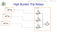
The first application is where you have multiple trip sources with one trip output relay – e.g. there may be a diff relay, a Buchholz relay, a winding temp relay, a …… relay etc. all operating the one final trip relay. In order to provide flags indicating which caused the trip relay to operate, it was common practice to use a series current operated auxiliary relay (Device 74 shown below such as the MCAA series of relays). Since you wanted to make sure the trip relay (94) and the respective current operated auxiliary (74) to operate, you would use a high burden relay to get enough current flow in the series relay, even accounting for the possibility that perhaps there were two or three series relays that had to flag if they all operated simultaneously. The availability of all initiation flags on the same Tripping Panel as the Trip relay therefore makes fault response far more efficient.
The second application requirement for High Burden Trip relays is for Capacitive Discharge Immunity. Under the specification for trip relays issued by the Energy Networks Association (UK) Technical Specification 48-4 , this test is only a requirement for High Burden relays in respect of 48 V d.c. and 110 V d.c. systems. The scenario is where there is extensive d.c. wiring from the protection contacts to the trip relay coil. The d.c. wiring can develop high capacitive charge with respect to earth or the negative wire on an unearthed system. If there is an insulation failure of the d.c. wiring, that charged capacitance can discharge through the trip coil and cause an unwanted trip relay operation. The High Burden means that more capacitive discharge current is required to cause operation and hence the system is more immune to such unwanted operation.
You may then of course ask why the Capacitive Discharge Immunity test is technically only for 48 and 110 V d.c. systems? It seems apparently simply because it was considered that lower voltage d.c. systems would not likely have such extensive wiring as to create large "stray" capacitance and hence inherently limited the instantaneous discharge current.
Blow‑Out‑Magnet Tripping Contacts
Circuit breaker 52T trip coils can be substantial mechanisms in their own right - quite often extremely high burden in themselves because of the mechanical forces they are operating.
These high burdens can be well in excess of the "carry continuously" or even "break" duty ratings of the relay contacts operating the 52T coil.
Most CBs have one of its own 52a auxiliary contacts in series with the trip coil so that once the CB has indeed opened as a successful trip, the auxiliary contact cuts off the tripping current.
This "ensures" the initiating relay contact is spared the necessity to break a high value DC current with inductive L/R of the 52T coil that would sustain an arc across the open contact. Such an arc could destroy, or at least damage, the tripping contact so that it may not work for the next time it is required to operate.
However if the circuit breaker 52a contact is itself not working properly (quite possible as a mechanical mechanism of the breaker), the trip current is not cut off.
This leaves the protection relay contact to carry the duty of "carry continuously" for latched relays, or necessitate the "break" duty when the trip relay relay self‑resets or is manually reset. When that happens the inductive arc is generated on the relay contact.
Consider a CB Fail event where the fault remains, CB 52a does not open.
Eventually the upstream CB is tripped by the CB Fail process thus clearing the fault.
But then the first protection resets and so now the protection relay trip contact is opening and breaking the high trip coil current with high L/R .
It is therefore necessary to use a blow‑out magnet on the trip contact that forces the arc outwards to increase the arc air distance to extinguish it and this preventing damage to the contacts.
Lock Out
The issue of Lockout is a bit different.
Lockout is about preventing closing of the CB until a potentially permanent fault can be checked and verified by personnel on site as to whether it is safe to close the CB.
These Lockouts are generally provided by contacts on the trip relay that have to be manually reset by personnel on site – the contact simply opens circuits the wiring to the close coil of the CB until it is reset. In some cases electrical reset is possible but the operation procedure would normally be that site personnel have to hand reset the unit but the remote electrical reset (e.g. via SCADA) can ONLY be done if the personnel have finished their job, left site but somehow forgot to reset the relay. Then, and only then, would the central control room staff be allowed to remotely reset the relay so they could close the CB.
Some Lockout relays therefore had a combination of self—reset and hand—reset contacts - the self-rest are used for the trip coil circuit whilst the hand-rest are used for the closing coil circuit.
So when it comes to Lockout it is a special safety issue. Modern electronic relays sometimes provide a setting which allows the output contact to latch and so can be used as a Lockout. Care must be taken in checking what happens to this Lockout when the auxiliary supply to the relay is removed - will it reset as a volatile output?
What happens when the relay is re-powered up? - will it still be in the Lockout state?
Is there a delay before it "remembers" the output is supposed to be latched in a different position as a Lockout.
Is it necessary/essential the Lockout is retained even though the DC auxiliary to the relay is removed? e.g. working on te panel but teh SCADA system may still have control of the CB close coil.
Copy this permanent link to this page: https://rhconsult.tiny.us/yvydwe5j
Contact Me
A phone call is nearly always welcome depending on the time of night wherever I am in the world.
Based in Adelaide UTC +9:30 hours e.g.
| April-September | Noon UK = 2030 Adelaide |
| October-March: | Noon UK = 2230 Adelaide |
Mobile + 61 419 845 253
Extra Notes:
Rod Hughes Consulting Pty Ltd accepts no direct nor consequential liability in any manner whatsoever to any party whosoever who may rely on or reference the information contained in these pages. Information contained in these pages is provided as general reference only without any specific relevance to any particular intended or actual reference to or use of this information. Any person or organisation making reference to or use of this information is at their sole responsibility under their own skill and judgement.
No Waiver, No Licence:
This page is protected by Copyright ©
Beyond referring to the web link of the material and whilst the information herein is accessible "via the web", Rod Hughes Consulting Pty Ltd grants no waiver of Copyright nor grants any licence to any extent to any party in relation to this information for use, copy, storing or redistribution of this material in any form in whole or in part without written consent of Rod Hughes Consulting Pty Ltd.