IDMT characteristic - what does it all mean?
| Rod Hughes Consulting General Web Site | Applications Home | Innovations and Solutions Home | A bit about Rod Hughes |
|
|---|
Note - if the navigation pane on the left of this window is not visible, click the 2-pane icon on the top bar
The IDMT relay, or rather IDMT element of a relay is the fundamental to the protection of all power systems in various different applications. Certainly below 66 kV it is extremely common as the principle protection system (a.k.a. but a poor choice of term "primary" protection as all protection protects the power system primary - the reference is between primary and back up form of protection)
IDMT curves have benefits for matching the maximum time before tripping to the thermal withstand of the equipment, i.e.. to allow maximum duration of operation before you have to trip to prevent damage.
An example of "special" inverse curve operation is motor protection where the IDMT curve is specifically set with two true thermal curves representing starting the motor from cold, or starting or running the motor "hot" after it has been running for some time. These motor protection devices also incorporate negative phase sequence into the thermal model due to the much lower thermal withstand and much higher damage caused by NPS.
Another example is matching the thermal withstand of transformers which are of course in general are permanently energised in a "hot" state.
However IDMT also serves to provide the fastest possible protection at any point whilst also providing graded "back up" protection for faults further downstream which could be seen by both relays as above their respective but different pick up settings.
Over the years (decades) the technology of IDMT operating devices has changed but the terminology often harks back to the original electromechanical technology pre 1980's, and hence can appear to be somewhat unusual.
IDMT - what does it mean?
An instantaneous relay or a Definite Time relay has a fixed operating time once current exceeds the setting e.g. if the setting is "1", then regardless of whether the current is "2" or "20", the operating time is the same.
An Inverse Definite Minimum Time (IDMT) function has decreasing operating time if higher values of current occurs above the pick up setting.
i.e. if the setting is "1", it will have a very long operating time at low current above "1" and very fast operating time when the current is "20".
Therefore the inclusion of the term “Inverse” makes total sense.
The slope of that inverse nature is defined in several different characteristic terms, and which are may be slightly differently defined in different Standards.
A fuse has a purely inverse nature characteristic based on I²t thermal affect on teh wire melting.
The so-called Extremely Inverse characteristic roughly corresponds to the fuse I²t characteristic, so we often find EI characteristics either side of fuses to achieve "good" grading.
But why “Definite Minimum Time for relays?
Well, consider that old electromechanical rotating disc relay … the laws of physics gets to a point where the disc just cannot spin any (appreciably) faster, no matter how much higher the current goes, so it has a Definite Minimum Time to operate.
This is in contrast to fuses where the wire just melts faster and faster as the current is higher.
Because there are literally millions of such relays probably still in service, when electronic relays came about they kept the same DMT philosophy – and by coincidence that, in some respects, made things hugely easier for the electronics engineers and programmers.
So IDMT characteristics of all technologies will have inverse characteristic up to a certain current, and then just go definite time.
Hence the term : IDMT
Plug setting, Pick up setting - what does that mean?
“plug” refers to the old electromechanical induction disc relays (e.g. CDG shown below) where the current setting was made by pulling out a metal plug/pin and inserting it in a different hole.
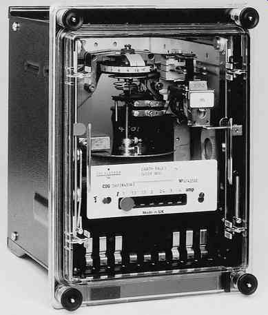
As technology changed, the Plug became rotary knobs, miniature “DIP” switches and then ultimately setting via a menu on the relay and/or via a communications port.


The current setting can be expressed in different ways:
e.g. consider a 5 A rated relay (for connection to a 5 A secondary rated CT)
If the electronic relay “knows” the CT ratio is say 200/5, it could be set as 300 A (primary)
Any technology relay could be set in terms of secondary amps e.g. set at 7.5 A (secondary)
It could be set in terms of % of rated current of the relay e.g. 150%
All three are the same setting, just expressed in different ways.
But if the CT ratio is actually 250/5, the setting would be 300 A, 6 A or 120% respectively.
Tripping current is not the plug setting
If we set the IDMT relay at "plug" 7.5 A secondary, and apply 7.5 A it will NEVER operate, i.e. the setting is the current that the relay is the highest current that the relay is guaranteed NOT to operate!
It is only by applying current above some percentage of that plug value will eventually cause the relay to close its trip contact.
e.g. applying the standard curve formulas, to a 7.5 A plug setting and current of 8.25 A (110% of plug) could take some 73 seconds seconds for an IEC 60255‑151 Standard Inverse (SI) curve, or 135 seconds for an IEC 60255‑151 Very Inverse (VI) curve, for the trip contact to eventually close.
This so‑called "closing current" is because the old electromechanical induction disc relays would start to spin at some current value, but it needed an even higher current to make it spin all the way round to close the trip contact.
In fact the old electromechanical relays would EVENTUALLY (100's of seconds or more) only trip when the current reached perhaps 110% of the plug setting for some IDMT curves, or 120% for other curves.
Hence depending on the relay and curve with a 7.5 A plug, the relay may not "trip" until the current is above 9 A!
This is also an important consideration to differentiate "overload relays" intended to operate when the current is upto say 5 or 10% above rating, and "protective relays" intended to operate for fault currents perhaps 20 x rated.
The exception was some “special” induction disc relays which were unusually calibrated as 100% closing curve mainly found in one particular older utility in Australia … sometimes called the “2.7 second” curve c.f. a normal "Standard Inverse" with operating time of a “3-seconds at 10 times the plug value. There was some very proprietary "black magic" manufacturing processes that changed a standard relay to have this 100% closing characteristic.
A further implication of the "will not operate at that plug current" with the disc perhaps "stopped" part way around, is that the reset current was well below the plug setting and even harder to define across the various manufacturers..
When electronic relays came along, the laws of physics no longer played a part in determining the force to get the disc to move off its back stop or the force needed to rotate the disc all the way around.
That closing current became ~105% of setting.
This all means you have to be very careful when grading electronic and induction disc relays to know what will actually cause contact closure of each.
Plug Setting Multiplier, Multiple of setting - what does that mean
PSM simply means the actual current magnitude with respect to the relay setting whatever technology the setting is made.
PSM= (Actual current)/Setting
If the setting is 300 A primary and actual current is 1200 A gives PSM = 4
If the CT is 200/5 and the setting is 7.5 A
1200/(200/5) = 30 A CT output
PSM = 30 / 7.5 = 4
If the setting is 150% of rated
1200/200 = 600%
PSM = 600% / 150% = 4
Time Dial Setting, Time Multiplier Setting
The Standards define operating curves at a certain magnitude of current with respect to the plug setting.
e.g. a Standard Inverse so-called 3-second curve has an operating time of 3 seconds at 10 x setting and 10 seconds at 2 x setting.
In the electromechanical relays, you could reduce that operating time by turning a dial on the relay. The dial would move the backstop (the resting position of the disc with current below setting) towards the trip contact. This reduced the amount of rotation, and hence time, it would take for the disc to rotate to operate the trip contact. Since the speed fo teh disc was proportional to the current, the time dial value applied to the whole characteristic regardless of current magnitude.
The term "Time Dial Setting" ( TD or TDS) was also referred to as Time Multiplier Setting (TMS). The value was from 0 to 1. So a standard 3-second operating time at 10 times plug setting could be reduced to say 0.3 seconds with a TMS of 0.1.
Origin of the Types of Curves
Different Standards have similar but slightly different curve definitions.
Whilst the Standards have specific formulas to define the curves, it is useful to understand the origin of the various curves themselves.
Again harking back to electromechanical days before the Standards such as BS 142, the manufacturers created their proprietary induction disc movement which all operated same laws of physics to operate. However they used their own coils, their disc material and their brake magnets. As such their characteristics were different.
In order to provide some standardisation, the curves of the various manufacturers were "averaged" to establish the particular standard shape..
They were not based on formulas as such.
The accuracy bands along the curve reflected the various proprietary deviations that would still meet the Standards.
In the process of updating of Standards, the curves were converted into formulas as we know today.
| 10 x setting Tms 1 | 2 x setting Tms 1 | |||||
| IEC Factor name | k | c | a | |||
|---|---|---|---|---|---|---|
| IEEE Factor name | A | B | p | tr | ||
| IEC 60255‑151 Standard Inverse | 0.14 | 0 | 0.02 | 2.971 s | 10.029 s | |
| IEC 60255‑151 Very Inverse | 13.5 | 0 | 1 | 1.500 s | 13.500 s | |
| IEC 60255‑151 Extremely Inverse | 80 | 0 | 2 | 0.808 s | 26.667 s | |
| IEEE C37.112 Moderately Inverse | 0.0515 | 0.114 | 0.02 | 4.85 | 1.207 s | 3.803 s |
| IEEE C37.112 Very Inverse | 19.61 | 0.491 | 2 | 21.6 | 0.689 s | 7.028 s |
| IEEE C37.112 Extremely Inverse | 28.2 | 0.1217 | 2 | 29.1 | 0.407 s | 9.522 s |
Drawing IDMT or DT curves
NEVER draw a relay curve dropping vertically to “zero” above maximum fault current.
The curve just stops at the maximum fault current because by definition the current cannot get any larger.
The operating time certainly never becomes zero because by definition there is a Definite Minimum Time or Definite Time of operation.
If the max fault level increased you would have to extend the curve further.
Relay technology
Electromechanical devices inherently obey physical laws related to the analogue value of current directly.
The first electronic relays of course were electronic components (resistors, capacitors, inductors, transistors and diodes) working with analogue signals.
So you could calibrate easily because peak of a sinewave was 1.414 x the r.m.s.
So now the relay manufacturers have to apply various filters.
Some may have used the average over a half cycle (average of a full cycle is 0).
Some may operate on the basis of the peak signal.
Some may have used full wave rectified signal.
.
In the early 1980's along comes digital devices. Digital can mean two different things
- purely being positive or negative or being above or below a certain value (simple 1 or 0 at any instant)
- creating a hexadecimal number representing the value at a certain sampling period - typically 80 or 96 samples per cycle, even faster for certain vendors and/or applications.
Or they could operate on the r.m.s. calculated over half or full cycle based on thos esamples.
These digital relays used various means to provide their operating mechanism (no apology for being a "GEC man" in my early days - the other vendors had other types) e.g.:
- The revolutionary Micromho SHNB distance relay used a sequence comparator based on the relative sequence of the zero crossings of the current c.f. the polarising signal.
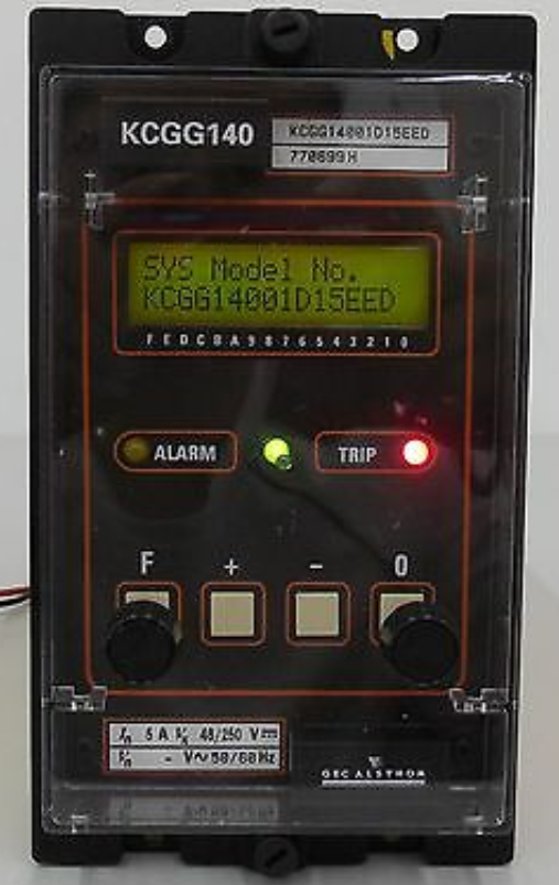
- The revolutionary "world's first microprocessor based relay" MCGG, and later KCGG for example used a logarithmic look up table to determine the operating time based on that hexadecimal number.
- The revolutionary MBCH Transformer Differential used a "gap detector" with the analogue value given a value of "1" above the certain threshold magnitude and "0" below and then determining how long it was "0".
In the late 1980's these digital devices also started to provide some form of communications interface to SCADA.
Then in the 1990's, digital went one step further and became fully numeric where an actual algorithm formula (such as provided in IEC 60255‑151) to determine the operating time of the relay.
- Protection Systems Engineering
- IEC 61850 Engineering
I provide a range of courses for company-specific in-house training and occasional public invitation courses. Contact me for details.
Contact Me
A phone call is nearly always welcome depending on the time of night wherever I am in the world.
Based in Adelaide UTC +9:30 hours e.g.
| April-September | Noon UK = 2030 Adelaide |
| October-March: | Noon UK = 2230 Adelaide |
Office + 61 8 7127 6357
Mobile + 61 419 845 253
Extra Notes:
No Waiver, No Licence:
Rod Hughes Consulting Pty Ltd accepts no direct nor consequential liability in any manner whatsoever to any party whosoever who may rely on or reference the information contained in these pages. Information contained in these pages is provided as general reference only without any specific relevance to any particular intended or actual reference to or use of this information. Any person or organisation making reference to or use of this information is at their sole responsibility under their own skill and judgement.
This page is protected by Copyright ©
Beyond referring to the web link of the material and whilst the information herein is accessible "via the web", Rod Hughes Consulting Pty Ltd grants no waiver of Copyright nor grants any licence to any extent to any party in relation to this information for use, copy, storing or redistribution of this material in any form in whole or in part without written consent of Rod Hughes Consulting Pty Ltd.