PX ClassPX is generally used in circulating current Merz-Price current differential schemes - in simple terms two CTs - one incoming and one outgoing of the zone - and they are connected in parallel.
As such during normal load conditions the current circulates around the two CTs - therefore there is no relay burden connected to them for 'normal' load or through fault current so it is pointless to specify a burden in the CT spec.
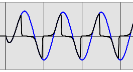
Furthermore, we design differential relays to have "no" current in the relay during normal load or through fault, but when there is an internal fault the current is perhaps 20x rated current flowing into the relay. Hence the accuracy of the CT differential current flowing into the relay is essentially irrelevant as it is going to be perhaps 1000 x the pick up setting of the relay (e.g. Ifmax = 20 A, Ipickup = 0.02 A) We also know for HiZ diff, during internal fault the CTs will saturate HEAVILY so the r.m.s. accuracy is totally irrelevant since the waveform looks much like this:

Blue line is expected unsaturated output,
Black line is saturated output due to excessive burden
(based on IEEE tool: https://www.pes-psrc.org/kb/published/reports.html then look for 2003 "CT Saturation Theory and Calculator" )
What we do need during load or external fault conditions is that CTs on each 'leg' of the differential circuit must produce EXACTLY the same current otherwise the difference would flow into the relay (or be calculated by the relay from independent inputs as representing a differential current) and hence possibly cause a trip - this is precisely what we DON'T want for through current conditions - we don't care if it is "inaccurate" as a ratio but they must both be the same "inaccuracy".
Recognising that there will always be some inaccuracy of the CT output, the only way to ensure the CTs that are being connected in parallel are all "identically inaccurate" over all current magnitudes is to specify the physical construction of the CTs.
This applies to CTs for physically or "numerically" paralleled for all the CTs: - in different bays for busbar protection; or
- for Restricted Earth Fault differential; or
- at each end of winding differential on rotating plant; or
- at each end of a line differential application.
The physical construction of PX CTs is indicated by these four factors: TURNS ratio
(eg 2000 A / 5A = 400)
| Excitation
current
(Amps) |
| Kneepoint
voltage
(Volts) | Winding
Resistance
(Ohms) |
|---|
| 400 | 0.02 | PX | 100 | 0.5 |
P Class CT
On the other hand, P class CTs are all about connecting a relay to a single CT usually in a Holmgren type connection.
In that situation we want to make sure the current is accurately represented on the secondary up to the maximum multiple of rated current for a particular value of burden within a certain accuracy.
Hence P class specifies things that relate to the connected load
| CURRENT Ratio | Rated Burden (VA) | Accuracy
(%) |
| Accuracy
Limit
Factor
(multiple of
Rated Current) |
|---|
| 2000/5 | 15 VA | 5 | P | 20 |
Beware of obsolete Australian Standard AS1675 P classAlthough it looks very similar specification terms, AS 1675 P class CTs are VERY different.
The hint as to whether a given P class reference is AS 1675 is usually that AS 1675 does not mention the term VA after the ratio, and there is usually two terms after the P because the Voltage has been inserted (not always as the ALF is sometimes optional or inferred i.e. 5P60 does not mean an ALF of 60 x rated).
The equivalent for the above 2000/5 15 VA 5P20 would be
| CURRENT Ratio | Accuracy
(%) | | Maximum
Terminal
Voltage
(Volts) | Accuracy
Limit
Factor
(multiple of
Rated Current) |
|---|
| 2000/5 | 5 | P | 60 | F20 |
AS 1675 : 1986 includes a converter in Appendix H :  click to enlarge click to enlarge
|