Current Transformer Theory Overview
| Rod Hughes Consulting General Web Site | Applications Home | Innovations and Solutions Home | A bit about Rod Hughes |
|
|---|
Note - if the navigation pane on the left of this window is not visible, click the 2-pane icon on the top bar
Selection and performance of Current Transformers are critical to protection system performance.
Physically a CT is made up of an iron core and windings
Physically a VT is made up of an iron core and windings
So emf and all sorts of Laws must apply equally to both - there is not "magical" iron and no "magical" copper being used in either CT or VT.
But the first LAW we learn in electrical engineering is Ohm's Law V=I x R
Electricity flow anywhere MUST adhere to this Law.
We also know that in an ideal CT, both the Ampere-Turns balance and the Volt/Turn balance must be maintained primary to secondary i.e.:
- Ap x Tp = As x Ts
- Vp/Tp = Vs/Ts
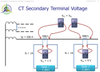
Two identical CTs with the identical current flowing through their primary windings is a great use case which brings us back to the absolute fundamental principle of electricity as Ohm's Law.
 Click to enlarge
We have a CT primary current flow through the CT primary winding resistance.
By Ohm’s Law the voltage that this current develops in flowing through that primary winding impedance is V=I.R
Since the bus bar or cable passing through the CT is exactly the same for both CTs, they have the same R
So the same R and the same I means the same Vp on both CTs.
No escaping that.
Since the primary current is rated 500 A, and the P class CT is generally designed that it won’t saturate (or rather will maintain accuracy) until at least 20 x rated current, both CTs will produce rated secondary current of 1 A.
No escaping that.
The left-hand CT will push its 1 A output through the 1 ohm burden.
Therefore it will have the voltage generated BY THE BURDEN at its terminals that can be physically measured as Vs1 = I x R = 1V.
No escaping that.
The right-hand CT will push its 1 A output through the 5 ohm burden.
The voltage at its terminals is also develop BY THE BURDEN as Vs2 = 1 x 5 = 5V
No escaping that.
There is nothing “magical” or any other Law for either CT that could obviate Ohm’s Law applying in these conditions.
The outcome is that one CT has a voltage transformation of Vp/1 V whilst the other identical CT has a voltage transformation ratio of Vp/5 V
Vp/Ns1 is not equal to Vp/Ns2 even though the CT is physically identical and the primary current is identical.
Still can’t get away from that!
The Volts/Turn Law appears to have been broken!
But has it?
The Volts/Turn primary must equal the Volts\/Turn secondary.
But the Volts/Turn in this equation is NOT referring to the secondary TERMINAL VOLTAGE
It is referring to the internal voltage which is developed according to the formula E = 4.44fNaB formula.
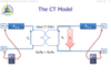
CT equivalent circuits are generally shown in this manner:
 (Click to enlarge)
We can see then that there is a difference between the voltage measured across the CT terminals and the internal voltage developed by the ideal CT simply because of the CT winding resistance and the output current of the CT.
The next thing is then to understand what is the Knee Point Voltage which is described here: Current Transformer: What is Kneepoint Voltage?
(Note the old Australian Standard AS 1675 used to specify its P class CT as the CT terminal voltage i.e. a 10P150 F20 meant the CT will perform correctly up to 20 times rated current with 10% accuracy and will be able to generate Vs = 150V at its terminals at 20 x rated current – i.e. the max burden is 7.5 ohms. Personally I prefer this than the new standards aligned to IEC)
Contact Me
A phone call is nearly always welcome depending on the time of night wherever I am in the world.
Based in Adelaide UTC +9:30 hours e.g.
| April-September | Noon UK = 2030 Adelaide |
| October-March: | Noon UK = 2230 Adelaide |
Office + 61 8 7127 6357
Mobile + 61 419 845 253
Extra Notes:
No Waiver, No Licence:
Rod Hughes Consulting Pty Ltd accepts no direct nor consequential liability in any manner whatsoever to any party whosoever who may rely on or reference the information contained in these pages. Information contained in these pages is provided as general reference only without any specific relevance to any particular intended or actual reference to or use of this information. Any person or organisation making reference to or use of this information is at their sole responsibility under their own skill and judgement.
This page is protected by Copyright ©
Beyond referring to the web link of the material and whilst the information herein is accessible "via the web", Rod Hughes Consulting Pty Ltd grants no waiver of Copyright nor grants any licence to any extent to any party in relation to this information for use, copy, storing or redistribution of this material in any form in whole or in part without written consent of Rod Hughes Consulting Pty Ltd.