| Rod Hughes Consulting General Web Site | Applications Home | Innovations and Solutions Home | A bit about Rod Hughes |
|
|---|
Note - if the navigation pane on the left of this window is not visible, click the 2-pane icon on the top bar
Converting Measured Values to Sequence Components
Analysis spreadsheet to download
This spread sheet provides a tool for converting the 3-phase phasors into their Sequence Components.
Click to download the spreadsheet: Sequence Components.xlsx
Positive, Negative and Zero Sequence Components are often a key aspect of analysis of power system conditions.
Any set of three phase measurements of Magnitude AND Relative Phase Angle between the phasors can be analysed using the Sequence Component Formulas
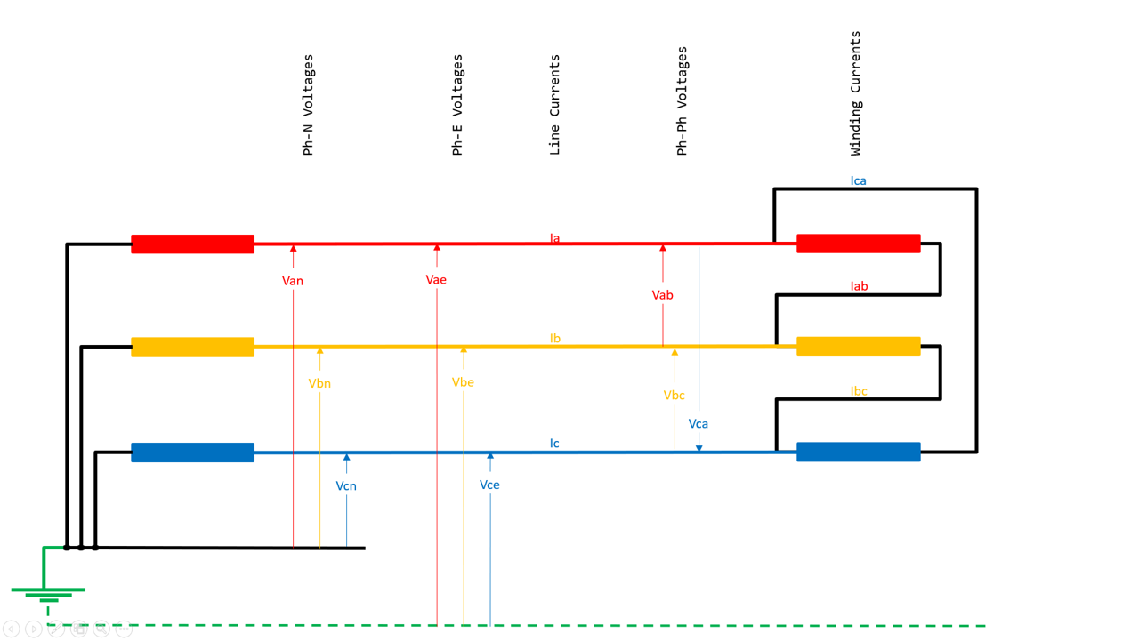
Consider three phase measurements as
- A = A_magnitude @ A_angle (A_angle is with respect to the reference angle, but is often set as the reference phasor at 0°)
- B = B_magnitude @ B_angle (B_angle is with respect to the reference angle)
- C = C_magnitude @ C_angle (C_angle is with respect to the reference angle)
where the measured values are magnitude and relative phase angle values compared to the reference 0° angle.
Note these relative phase angles are NOT the phase angle associated with Power Factor.
Power Factor angle refers to the relationship between voltage and current which is distinctly different to the angle relationship between the three currents or angle relationship between the three voltages.
The angle here is between three current phasors, or the angle between three voltage phasors
There is a mathematical "operator" α = 1 @ 120°, i.e. this effectively rotates the phasor by 120°, α² rotates by 240°.
These formulas allow us to derive nine Sequence Component Phasors for the A phase as follows.
- Positive Sequence A1 = ( A + αB + α²C ) / 3
- Negative Sequence A2 = ( A + α²B + αC ) / 3
- Zero Sequence A0 = ( A + B + C ) / 3
Similar formulas apply for the B and C phases, i.e. for a 3-phase set of measured phasors, there are 9 individual sequence component phasors.
Positive Sequence (generally designated as a suffix "1")
By definition, the three phase values of positive sequence are the same magnitude and precisely 120° apart and rotate in the forward sequence ABCABCABC
A1 = A1_magnitude @ A1_angle
B1 = B1_magnitude @ B1_angle
C1 = C1_magnitude @ C1_angle
where
- A1_magnitude = B1_magnitude = C1_magnitude
- B1_angle = A1_angle - 120
- C1_angle = B1_angle - 120
Negative Sequence (generally designated as a suffix "2")
By definition, the three phase values of negative sequence are the same magnitude and precisely 120° apart, BUT they rotate in the reverse sequence CBACBACBA
A2 = A2_magnitude @ A2_angle
B2 = B2_magnitude @ B2_angle
C2 = C2_magnitude @ C2_angle
where
- A2_magnitude = B2_magnitude = C2_magnitude
- B2_angle = A2_angle - 120
- C2_angle = B2_angle - 120
Zero Sequence (generally designated as a suffix "0")
By definition, the three phase values of zero sequence are the same magnitude and precisely in-phase, and rotate together.
A0 = A0_magnitude @ A0_angle
B0 = B0_magnitude @ B0_angle
C0 = C0_magnitude @ C0_angle
where
- A0_magnitude = B0_magnitude = C0_magnitude
- A2_angle = B2_angle = C2_angle (all in phase)
Analysis examples
For a balanced condition, all phases are equal magnitude and 120 degrees separation in the right sequence and would therefore be analysed as pure Positive Sequence, no Negative or Zero Sequence. This would remain true at any value of the balanced phasors and hence we must take care in setting protection functions not to operate for balanced loads from zero to rated values, and knowing that even large changes below rated values are not necessarily indicative of an actual fault.
However if the phasors become unbalanced for any reason ,i.e. no longer equal magnitude and/or no longer 120 degrees separation, Negative Sequence and/or Zero sequence will be seen which will be a very clear indication of some kind of fault - they are normally zero but become non-zero. Hence some functions are assigned to operate on the basis of Negative Sequence detection changing from zero. Of course Zero Sequence detection has always been available as the earth fault element. Older electro-mechanical relays required complicated extra hardware filters to extract Negative Sequence component. The advent of numerical relays has provided easier detection of Sequence Components using algorithms.
Sequence Components are mathematical analysis of a set of three phasors. They are not "real" world physical measurements. You cannot connect a multi-meter to any point and measure a Sequence Component!
Even if you use a multi-meter to measure all three phases as the same magnitude, you also need to know they are exactly 120° apart to know that the values are balanced and therefore would be the Positive Sequence value with no Negative or Zero Sequence component.
- The "closest" you get is if you know there is no current in two of the three phases but current in the third, you know the third current is 3 x the Zero Sequence.
- Or if you measure the current in the earth-neutral leg, that current is 3 x the Zero Sequence.
- Or the current in the delta itself is the actual Zero Sequence value IF all three windings are the same magnitude AND they must also be in-phase (consider a Dyn TF with balanced load .. the D winding currents are all the same magnitude but not in-phase).
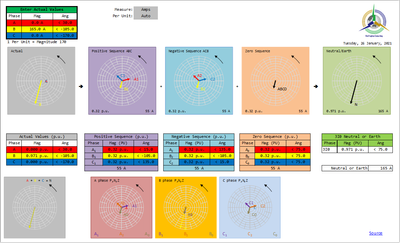
Example 1: Balanced 3-phase
This is all positive sequence

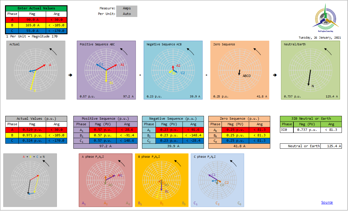
Example 2: general unbalance magnitudes and angles
This results in a full set of Sequence Components
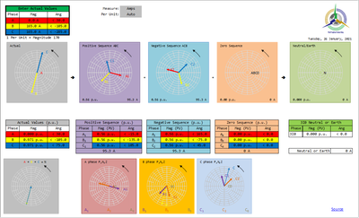
Example 3: a single phase condition (single phase load or single phase-to-earth fault)
This would result in these components (e.g. the star side of a Dyn transformer with a single phase load or fault on the star, or the currents in the delta windings):
Example 4: a phase-to-phase condition (fault or delta-side of TF with single phase condition on star-side)
This would result in these components: (e.g. the line connections to the delta side of a Dyn transformer with a single phase load or fault on the star)
Example 5: equal phase magnitudes but unequal single-phase Power Factors
e.g. assuming the phase-to-neutral voltages are all balanced at 120 degrees apart and A phase voltage is reference 0°:
A_phase 0.95 lagging (-18°) means the A phase current phasor is at -18° with respect to the A phase voltage,
B_phase 0 PF, means the B phase current is in phase with the B phase voltage, i.e. at -120° with respect to the A phase voltage,
C_phase 0,85 leading (+31°) means the C phase current is leading the C phase voltage by 31°, i.e. -209° with respect to the A phase voltage

Sequence Components and Delta/Star transformers
A common question when first dealing with Sequence Components is : How are Zero Sequence current eliminated in delta windings.
First you have to remember that Sequence Components are not “real” – they are mathematical derivations from the real currents, but the sum of all Components add up to equal the real currents.
Hence for a set of 3 phase phasors, there are nine Sequence Component phasors: 3 x Positive Sequence, 3 x Negative Sequence and 3 x Zero Sequence.
Second, real currents must obey Ohm’s Law and Kirchoff’s Law … they must have a path to flow.
So do Sequence Components, but the real paths have to be converted into equivalent Sequence Component paths and equivalent Sequence Component impedances, although that is not the focus of this information.
YNyn
Consider a low voltage star winding of a transformer.
Single phase current can flow if there is a connection to the star (neutral) point of the transformer …
- 4‑wire systems of course mean single phase loads can have current in one phase flowing back via the neutral wire.
- 3-wire, or 4-wire systems with earthed neutral will allow single phase earth fault currents to flow in one phase flowing back via the earth.
So the real current distribution of a single phase condition (load or earth fault), the three phases would be termed “1-0-0”.
Refer Example #3 above.
With current in one phase, the Sequence Component Analysis shows that there is Positive, Negative and Zero Sequence current flowing in all three phases and they “flow” through the equivalent three phase Positive, Negative and Zero Sequence path impedance of each phase, even though the real impedance on the two phases with zero real current is effectively an open circuit.
The A, B and C zero sequence currents would all add up to be the value of the real current because as zero sequence they are all in phase.
i.e. I-single-phase = 3 x I-zero-sequence
So now consider that single phase LV current in a star winding for a YNyn arrangement, i.e. neutral connections on both windings
On a star HV winding, that LV current must cause equal Ampere.Turns balance on the HV winding, i.e. real current in one LV winding needs to cause real current in one HV winding to maintain Ampere.Turns balance.
Being a star HV winding arrangement, there can only be current flowing in one HV winding corresponding to the LV winding with real current flow. There can be no current in the other two HV windings because there is no current in the other two LV windings.
That being the case, then the real HV currents would also be termed “1-0-0” distribution and would also be analysed with Positive, Negative and Zero Sequence components.
Dyn
If the HV winding is delta, i.e. Dyn, Ampere.Turns must still balance LVwinding-to-HVwinding.
So one of the delta limb windings will have current flowing to balance its corresponding LV winding.
At each bushing there are three connections – two winding ends and the line.
Kirchoff’s Law is that the sum of the currents in and out of a node must equal zero.
We know that one winding has current flow, the other winding has none, so the current flow must be on the line connected to the node.
That happens because when you look at the currents in the windings (i.e. not the line currents), the winding currents are still “1-0-0” due to Ampere.Turns balance.
That HV winding current can only flow into the TF bushing from one phase connection and out on another phase connection at the other end of the winding, i.e. there is line current flowing "into" the bushing on A phase and out of the other bushing on B phase.
We would therefore term the line currents as a “1-1-0” where the two line currents are equal magnitude and opposite directions.
If you now do the Sequence Components of a “1-1-0” as in Example #4 above, you will see that there is only Positive and Negative Sequence … no Zero Sequence at all.
We therefore say that the Delta winding is a "Zero Sequence Trap".
The delta winding currents ar "1-0-0" distribution to achieve Ampere.Turns balance with the LV windings. That means that within the windings, there are Positive, Negative and Zero Sequence components.
Therefore the magnitude and phase angle of the A winding, B winding and C winding Zero Sequence currents are all exactly the same.
Therefore applying Kirchoff’s Law, if the current flowing into the node from one winding equals the current flowing out of the node into the other winding, there can be no Zero Sequence current flowing on the line as proven in the previous paragraph.
All the Zero Sequence currents happily flow around the HV Delta winding, but do not flow on the HV line phases.
Hence the Delta has "trapped" the zero sequence current.
(For the same reason, delta windings are also a 3rd harmonic trap as the 3rd harmonics are inherently in phase.)
But note: a common misunderstanding is that Delta windings do not result in any zero sequence current .. ever!
If you have an earth fault on the HV delta winding,.., in the worst case say a bushing to earth, there will be current flowing down the one line to the faulted bushing. That would still be “1-0-0” so Zero Sequence still exists. Mid-winding faults would be more complicated with real currents flowing in all three lines, but will still analyse as having some Zero Sequence.
Contact Me
A phone call is nearly always welcome depending on the time of night wherever I am in the world.
Based in Adelaide UTC +9:30 hours e.g.
| April-September | Noon UK = 2030 Adelaide |
| October-March: | Noon UK = 2230 Adelaide |
Office + 61 8 7127 6357
Mobile + 61 419 845 253
Extra Notes:
No Waiver, No Licence:
Rod Hughes Consulting Pty Ltd accepts no direct nor consequential liability in any manner whatsoever to any party whosoever who may rely on or reference the information contained in these pages. Information contained in these pages is provided as general reference only without any specific relevance to any particular intended or actual reference to or use of this information. Any person or organisation making reference to or use of this information is at their sole responsibility under their own skill and judgement.
This page is protected by Copyright ©
Beyond referring to the web link of the material and whilst the information herein is accessible "via the web", Rod Hughes Consulting Pty Ltd grants no waiver of Copyright nor grants any licence to any extent to any party in relation to this information for use, copy, storing or redistribution of this material in any form in whole or in part without written consent of Rod Hughes Consulting Pty Ltd.