There are architectures and architectures - put a protection engineer in a room with a network engineer and you could quickly get 30 different topologies - all valid in their own right!!  Substation networks, particularly using IEC 61850 equipment, have to fundamentally support the critical real-time signals associated with protection. Depending on what 'extent' of IEC 61850 is being implemented, the performance requirements of the network will vary. Then there is the question of not just redundancy (RSTP provides a redundant path in a ring arrangement), but also provision of full physical duplication (star or ring), For quite some time, duplicated RSTP was a common philosophy applied to network architectures. However, even medium sized RSTP networks can take 100 ms or more to recover so perhaps a protection operation or CB Fail would effectively be out of service, or have impaired functionality) for that long. Even more so if Sampled Value weren't arriving continuously and therefore may disrupt the protection algorithms themselves. Such concerns are addressed by so-called "bumpless" architectures defined in IEC 62439-3 as HSR and PRP. PRP and HSR are two ways bumpless can be implemented, but be careful what you wish for in cost, configuration, maintenance, fault finding - straight out duplication with bumpy systems that are engineered to not-maloperate whilst going over a bump may be easier in some cases. The following sections give a brief description of each of the RSTP, HSR and PRP arrangements. Finally an optimized PRP with dual RSTP solution is presented with a Failure Mode Effects Analysis.  Rapid Spanning Tree Protocol RSTPRSTP has the IEDs connected to a network switch usually via a single communications port. The protocol itself and the configuration is within the switches i.e. primarily it is a switch-based protocol for managing the ring and the IEDs are essentially not affected in any way. Usually the IEDs are single port devices (Single Attached Nodes) but may be dual port (Dual Attached Nodes using Dual Homing where only one port is active until a failure is detected) These switches are then connected in a ring. 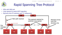
The switches around the ring are automatically managed to select one link as an "open" link i..e it is effectively switched off so that messages can get round the ring to all switches but not keep circulating "forever". When a failure in the ring is detected, the ring automatically re-configures to turn the open link back on to restore the communication to all switches. There is some "recovery time" associated with that reconfiguration depending on the switch may be as low as 5 ms per switch which may add up to well over 100 ms in large networks. This represents a "bump" in the continuous message flow to the IEDs High-availability Seamless Redundancy HSRHSR is defined in IEC 62349-3 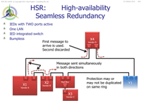
HSR eliminates the separate network switches with the IED effectively implementing switching protocols. HSR is therefore clearly an IED-implementation protocol. The IEDs themselves must have two ports and the comms link is directly looped IED-to-IED as a complete ring. The IEDs send their messages simultaneously in both directions "left" and "right" around the ring. Each other IED will work on the basis of the first message it receives from either direction and then continue passing the message on to the next IED in the ring. Eventually the IED will receive the duplicate message from the other direction. It will still work on the basis of the first of the duplicate messages received and hence it is considered a "bumpless" arrangement requiring no ring reconfiguration as with RSTP. The sending IED knows when it receives its own message back and then doesn't pass it on again as it has already done a full loop of the ring. - All IEDs in the ring to support HSR - i.e. they ALL MUST have 2 ports, and therefore more expensive than single port IEDs
- There is a limit of the number of IEDs in any one ring - generally around 50 but may be limited by the "weakest" IED limitation to perhaps only 20 or so - this then requires 4 x REDBoxes (redundancy Box) or dual QuadBox to interconnect two rings
- All IEDs must have the inbuilt functionality of the HSR process which is probably also going to be more expensive.
- You may find a function that you need which is not supported by any box that has HSR - this needs an additional HSR network Redundancy Box ("Red Box") which then ironically you haven't really achieved full HSR if the cable between the single port IED and the Red Box interface fails.
- But you can save on the number of network switches you buy
- ..... and a few more issues
Parallel Redundancy Protocol PRPPRP is defined in IEC 62349-3 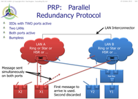
PRP IEDs are connected as two ports, each port connected to a completely different network. The protocol is implemented in the IEDs themselves and the switches are therefore "standard switches". The type of network on each "side" A and B can be anything - i.e. could be star network, RSTP network or HSR network on side A, and side B could be chosen independently to be star network, RSTP network or HSR network - noting that if a side is implemented as HSR that means two ports for that side. So in principle if the IEDs support it, side A could be RSTP and side B could be HSR. The IED sends its message on both sides simultaneously. The other IEDs should receive both messages on their two ports but obviously will just work on the basis of the first message received. If there is a failure of one of the networks, the IED will still receive the other message via the alternate side and so will have "bumpless" continuity of messages - not all IEDs have to support PRP - i.e. only the ones you want dual connected to both LANs so that is a potential saving e.g. condition monitoring or general substation controls (lighting, gates ..) may only need to be connected to either the A or B side.
- The PRP IEDs need to have 2 ports (Dual Attached Nodes) so more expensive than traditional Single Attached Node devices
- PRP Redundancy Box ("Red Box") provides a means to connect Single Attached Node IEDs to PRP networks, however then ironically you haven't really achieved full PRP security if the cable between the single port IED and the Red Box interface fails
- Need up-to double the number of switches as duplicate networks
- May still need a dual port interface for single port devices - so not really PRP as far as that IED is concerned.
Note you could go the full hog and have the two PRP LANs as HSR!! Now we are really getting serious reliability against any bump ...
Be careful what you wish for and why?The National Electricity Rules in Australia require appropriate duplication of protection systems "and the communication systems upon which they depend"
Clearly LAN-based protection carrying Sampled Values and/or GOOSE have the protection heavily, if not 100%, dependent on the communications network! Does HSR provide duplication? If there is an X ring and a separate Y ring the answer is of course yes Does PRP provide duplication? If there are 4 LAN networks ( X-A, X-B, Y-A, Y-B) the answer is of course yes Fundamentally, independent duplication allowed us to have either system out of service for several hours - even for a bump of loss of power supply, a CT left short circuited, a VT fuse blown, a trip link left open.... - and we didn't need any of those to be routed via two different paths to duplicated inputs to the one protection IED. Sometimes simple is best (single ports) if the bump can be detected and the system engineered to not have a hiccup as a result. However the NER doesn't actually say "duplication" as the requirement... even though the industry generally achieves the objectives by hardware duplication of the relays, auxiliary supplies, current transformers and trip coils.
The NER actually says the primary protection system "must have sufficient redundancy" !! So with HSR and PRP both providing effective redundancy of the communication, this leads to the question: Is it acceptable to connect the the X and Y protections to the same network?
Has total independence from any common failure mode (network storming, incorrect VLANs config ...) been achieved? What if you want to take one IED out of service for testing - the HSR is broken and both X and Y is all sitting on a single path of communication.
Or what if a Y IED is sitting between two X IEDs in the HSR ring and the X power supply fails .. the X protection has obviously failed due to lack of power supply and this Y IED is effectively isolated from all communication resulting in failure of X and Y. PRP arguably seems to be better suited being two separate LANs. However with X and Y both connected to both LANs is there common failure modes there than can affect both since they are not totally independent. Of course with all bumpless systems, you must have good mechanisms engineered in to detect and report when one path has had a break, and good mechanisms to fault find as well as taking any part of the system out of service for maintenance of any part .. | Note |
|---|
| title | Time Synchronisation |
|---|
| Note that some arrangements of IEEE 1588 Precision Time Protocol systems may be incompatible with HSR/PRP networks - notably when there are two Grand Master clocks for redundancy. However the Best Master Clock Algorithm (BMCA) will arbitrate to only send the selected "master clock" as the consistent A and B signals to all IEDs, but still provide automatic redundancy if one clock fails |
Clearly whether you hold preference for HSR or PRP, blind adoption of bumpless technologies is not an appropriate strategy.
Well-considered engineering must be applied for consideration of how the system operates when things are healthy as well as how it operates when things aren't healthy or are under test. Is bumpless necessary?Worrying about "bumpy" RSTP vs "bumpless HSR/PRP" is a double contingency event issue i.e. a significant power system event happening whilst the RSTP ring is "re‑converging" ... a low probability perhaps and you would consider yourself somewhat unlucky to have that happen. However protection engineering philosophy tends to not work on probability of something not happening as we expect, but rather the INEVITABILITY of something going wrong EVENTUALLY ... that is why we duplicate systems. (In fact I investigated an incorrect operation affecting four HV substations spread over 160 km all blacked out in less than 0.5 s that would not have happened if any one of the seven critical problem factors had been correct i.e. ALL seven had to be incorrect for this event to have happened ... and it did! Duplication did not help because the seven conditions on the one system conspired to allow the trips ... or as some would say Murphy's Law .. but we would argue the risk of that was minuscule.) So whilst we might write off the risk as too low to have to worry about considering bumpless technologies, we have to weigh that against the economic impact on the grid (and its customers) if something fails to clear a fault in reasonable time with more consequential outage/damage than we would otherwise have allowed .. or incorrectly trips when it shouldn't! So consider a 130 ms re‑convergence of an RSTP ring means you will lose upto 8 GOOSE fast retransmits being received by some subscribers and it may be a further 100+ ms for the next GOOSE to actually be received when the loop re‑converges i.e. total missing information delay > 200 ms. 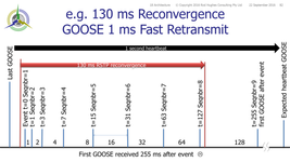
Potential impacts of new GOOSE status values not arriving for a period of 200 ms (which may still be within the expected 1-second heartbeat expectation): - Pxxx.Op failed to be received by XCBR = Trip delayed by 200 ms = Upstream protection grading compromised = Possible unwanted trip of upstream CB as well as local CB
- Pxxx.Op not received by RBRF = CB Fail initiate delayed by 200 ms = May impact overall critical fault clearance time compliance (e.g. HV/EHV ma not tolerate that additional delay in CBF operation)
- XCBR.pos not received by RBRF = RBRF may time out and trip bus as CB Fail
- Pxxx.str reverse blocking start not received by upstream Pxxx = Unwanted upstream Pxxx trip before local CB trip
This is the basis of FMEA - Failure Mode Effects Analysis - which needs to be done when designing systems.
Having said all that, we must remember that the low probability has been proven to be low simply because well over 8000 substations have been implemented on nothing better than bumpy RSTP simply because HSR and PRP did not exist when they were built and (touch wood) they have not suffered such a double contingency power system event during an RSTP reconvergence.
On the other hand, if we only thought about low probability, what is the real need for the fast re‑transmission cycle of GOOSE? i.e. how many times have these 8000 substations actually missed the first new GOOSE status value message when a status changes, let alone the second re‑transmit ... tenth re‑transmit? Why have an exponentially increasing delay on the fast re‑transmit - why not 5 messages all 5 ms delayed and the next 5 as 10 ms delayed - I mean they are important messages ... The proven statistics would show extremely low risk, but yet we make GOOSE operate in that way "just in case Murphy shows up..." If we look at things from an "Availability" point of view ... We duplicate systems just in case one system fails to work when it should, i.e. the duplicate system is still highly likely to work. Probability theory says that if you have a system with 99.9% Availability, then it has an Unavailability of 31536 seconds per year i.e. 8.76 hours when it might not work. That is actually pretty good for wire based systems taking into account MTBF of the IED, number of wires in series that might go open circuit (rodents/loose connections) and number of links in series that might get left in the wrong position … Duplicate that system in parallel, the combined availability to work when required is 99.9999%, which means a risk of only 31.5 seconds per year (0.5 minutes) when neither of the systems work. But that duplication does not stop a failure of something causing a maloperation happening in something else in that system i.e. something happening when it should not due to lack of / or incorrect combinations of input signals. That might happen in ether system and therefore they each remain with the possibility it might maloperate nearly 9 hours per year, total 18 hours per year of risk between the two of them. We had to live with that risk in wire based systems. However in LAN based systems we can reduce/minimise the risk of a failure making something happen that shouldn’t i.e. LAN based systems can deal with the issue that some missing incoming signals may cause a function to maloperate by using bumpless HSR/PRP to ensure that at least as far as LAN failures are concerned, missing signals don’t happen. An individual HSR/PRP systems will each end up more like say 99.999% Availability in their own right so each of the duplicated systems would only have 315 seconds per year (total of the two systems around 10 minutes) of possible maloperation due to lack of / incorrect combinations of input signals to a particular function. The question is then do you need to duplicate an HSR or PRP system? The answer is probably yes you still need to duplicate the systems, simply because HSR and PRP are contemplating failure of the LAN, however they do not compensate for complete failure of the publishing IED or the subscribing IED so that can only be handled by duplication. | Warning |
|---|
| However there is one aspect that must be carefully considered before rushing into bumpless implementation. Things are never not working! That may sound a strange concern as surely that is the objective!
Well it is ... except when testing devices and/or functions. Physical isolation of wire-based systems involved opening/closing links in the right order to provide safe access to the Device Under Test (DUT) and its Function Under Test (FUT). However LAN-based systems cannot be safely isolated by disconnecting a communications cable/fibre!
Other devices may depend on certain messages from the DUT or indeed the DUT may have certain Functions that remain in service whilst other functions are being tested.
IEC 61850-7-4 Ed 2 Annex A has provisioned certain mechanisms that enable such considerations so that the real "in-service" messages and the simulated messages will co-exist. If we now consider bumpless architectures, the isolation and test procedures must also consider how messages are injected into and detected within the system. |
Unlocking the Power, Redundancy and Resilience of PRP with dual RSTP rings (MSTP)One potential criticism of PRP is that to achieve full redundancy for X and Y protections, you would seemingly need four independent sets of LANs and switches - XProt-A, XProt-B, YProt-A and YProt-B. However if we consider the principles of protection redundancy is to ensure the protection systems will clear a fault reliably even with one piece of equipment in the system out of service, duplication is not necessarily required when applied to LAN architecture with duplicated PRP LANs on each. The following optimized architecture shows an IED system based on PRP with MSTP backbones to ensure that the IEDs operate in a bumpless environment.
Instead of having four sets of switches, it is characterized by having just the two "A-side" and "B-side" set of switches.
The total number of ports in the LAN switches remains the same being dictated by the total number of IEDs, but the X and Y IEDs connect to the same set of switches, thereby saving physical mounting space and the number of boxes to be managed. There are four backbone connections between each of the switches arranged as two independent RSTP rings on the A-side (RSTP ring A1 and A2) and two independent rings on the B-side (RSTP Ring B1 and B2). Operating two independent RSTP rings between switches is actually using the Multiple Spanning Tree Protocol (MSTP) configuration of the switches. Those connections are shown as individual Cat5/6 or fibre connections - most likely fibre having "back bone" bandwidth requirements. Fibres in particular may be provisioned as multiple fibres in the one cable to simplify installation, but it is still preferable to have at least two x two-core cables i.e. the two RSTP A1 fibres in one cable and the two RSTP A2 fibres in another cable. The IEDs are duplicated as X and Y systems right up to and including the gateways (usually operating in some sort of fail over selection to the central control center) and IEEE 1588 PTP V2 time synchronization Boundary Clocks. Naturally the HMI is not duplicated as an X and Y device, but there may in fact be multiple HMI's and/or test equipment permanently or temporarily connected at various locations in the network, if necessary using an IEC 62349-3 Redundancy Box (a.k.a. RedBox) if they do not directly support PRP. 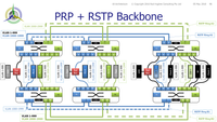
Naturally for ports to carry multiple VLANs they must be configured as TRUNK ports as well as all the Ingress and Egress rules correctly configured. Of course you can choose your own VLAN allocation in the allowable range 1 - 4095, and there may be a limit associated with the switch on how many VLANs can be configured to pass through one TRUNK port.
In this example, the RSTP A1 ring is configured to carry the XProt VLAN messages as VLAN 1000-1999 as well as the station "common" messages (e.g. SCADA, Clock, Condition Monitoring...) on VLAN 1-999.
The other rings are configured with different combinations as follows in order to provide some ready recognition for purposes of commissioning, auditing and debugging message flow :
Failure Mode Effect Analysis (FMEA): - The LAN switches have dual power supplies powered by the X and Y auxiliary supply systems so all six switches are able to continue to work regardless of loss of one DC system.
- Whilst each of the switches have a common CPU and backplane connecting all the modules which could therefore be seen as as a potential common mode of failure for all connections of that switch, this does not prevent the alternate PRP LAN side operating to maintain communication between all devices.
- It is preferable to maintain independence of the X and Y messages in this configuration that the two X backbone ports in each switch are created on a different module to the two Y RSTP ports in order that a module failure does not affect both RSTP rings.
- These two RSTP rings on each side are configured to carry different VLAN ranges so that the fibres themselves provide independent paths for the X and Y messages on both sides.
Perhaps the final consideration is the physical design of the switch. Clearly this arrangement requires dual independent power supplies and a modular arrangement for the ports. If those power supply or port modules are also live‑swapable / hot‑swapable, i.e. can be replaced with powering down the switch nor physically removing the switch from the panel, then even a failure of those modules can be easily fixed without disruption of the Substation Automation System. Hence this combined PRP/MSTP arrangement maximises the independent IED operation whilst ensuring bumpless communication even during Spanning Tree re-convergence. What this means is that even with both X and Y protections sharing the same LAN PRP infrastructure, apart from the IED itself failing, you have an N-2 redundancy of the LAN infrastructure before either the X or Y system is impaired. A single failure anywhere in the LAN still retains full X and Y operation. It would take a second failure for the X or Y protection to be impaired.
|