Obviously a CT is is just a transformer like any other and must obey fundamental Laws so you have to imagine a lot of things all happening at once. The first is that Ampere.Turns on the primary must equal Ampere.Turns on the secondary.
In order to generate Amps there must be flux linking the primary and secondary, and specifically the flux must be changing with time. The second Law is that the EMF (voltage) of a coil is given by
E = 4.44 f A B N
f being frequency,
A being cross section area of the core
B being flux density
N being number of turns This can be reversed to recognise that B = E / (4.44 f A N)
or in words, if we need to develop a certain voltage, there needs to be a certain flux density. The third is that the secondary winding is just a coil of copper wound round a lump of steel. To "magically" turn those into a CT needs Excitation Current, sometimes called Magnetising Current Next is Ohms Law V = IR Now lets mix them all together ... As a rough visual analogy, consider the core as a glass cup - we can slowly add water to the glass and we can see the level of the water will rise. If we pierce a hole at the bottom the water will leak out and the level will fall. Consider the level of water as the level of flux. As long as water level is below the rim of the glass cup the water level can be seen to vary. But when the glass is full the level stops changing - the glass cup can be said to be fully saturated with the maximum amount of water.
Similarly there is a maximum flux density in the cross section of the core where eventually it saturates. Now if there is a burden connected to the CT, we know there must be a driving voltage to push the output current through the burden.
That voltage is the "internal voltage" of the CT according to Vct = 4.44 f A B N But we can also apply Ohms Law in that the CT voltage is also
Vct = I x (Rct + Rb)
where Rct is the internal winding resistance of the CT
Rb is the connected burden (including the connection wire lead impedance) So we can see if we increase Rb we need more volts
(Note this is the internal voltage = the voltage at the CT terminals would just be Vterminal = I x Rb) To get more volts we need more flux and therefore more flux density B. But if the core is saturated we cannot develop more volts because the flux level is not changing So what happens now?
As the primary current is increasing from zero in the first half cycle, there is output current because the flux level is changing.
But if we need more flux beyond the max flux density, the flux level is not changing, there can be no output current.
So what we get is that the CT works for a few milliseconds until the core saturates, i.e. it is correctly producing output current, then suddenly when the core saturates, the current drops to zero because the flux level is not changing.
Hence we get a "shark fin" half cycle waveform like this
/|____
which then repeats in the negative half cycle. 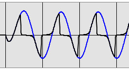
Blue line is expected unsaturated output,
Black line is saturated output due to excessive burden
(based on IEEE tool: httphttps://www.pes-psrc.org/kb/Reports/CT_SAT%2010-01-03.zippublished/reports.html then look for 2003 "CT Saturation Theory and Calculator" ) But we still require Ampere.Turns balance.
Where does all the expected output current go during the rest of the half cycle?
There is only one place, through the Excitation Path - this is modelled as a excitation impedance inside the CT connected in parallel to the winding. 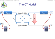 (click to enlarge) (click to enlarge)
As more flux is required, this impedance changes to draw more excitation current. Consider it as the "power supply" to the CT to make a lump of iron and a coil of copper wire to work as a CT. Normally it is just a few % of rated current. So with all the expected output current now only able to flow into the excitation path, what was just a few % of rated current in the excitation path, we now have the full maximum fault current. We now turn to the B-H curve of the CT. As the B increases, so does the H.
These are related to V and I
What we get is a curve that starts from zero with V increasing vertical axis and Iexcitation increasing horizontally and it is a "reasonably" linear slope. Then B gets to a point where the core is saturated, the V curve stops being linear and goes flat - it can't keep rising.
But the excitation current goes way off to the right to max fault current.
So so we get a plateau effect where the V stops increasing but the current goes way off to the right. Where that change in slope occurs is called the kneepoint.
(Down to the origin there is a small non-linearity where you need some excitation before the flux builds up so we call that the ankle point)
Hence if the CT internal voltage required is less than the kneepoint voltage, the CT is not saturated. The objective is therefore to make sure that the CT can develop enough voltage but less than its kneepoint voltage to drive the required output current through Rct and Rb
i.e we need to make sure Vkp >= Ifmax (Rct + Rb) This is simply interpreted in P class CTs as a maximum or rated burden expressed in terms of VA where VArated = Irated2 x Rbrated Provided you keep the actual Rb below the rated burden, the CT will not saturate up to at least the rated current x the Accuracy Limit Factor.
The ALF is simply ratio of the maximum fault current divided by the rated current. ALF = Ifmax / Irated |