Circuit Breaker Failure is a key element of any protection system. In general we always make sure there are at least two different systems capable of clearing any particular fault. In some cases that means full duplication of the protection system including CTs and battery supplies and that duplication has identical performance philosophy, i.e. X and Y (or Main 1 and Main 2 depending on your terminology) are nominally both expected to operate at the same time for any particular fault – all being healthy in those systems. In other cases that may mean a Main and Backup protection where the backup is time delayed in that the hope that the Main protection clears the fault successfully. That may be local back up associated with the same breaker or it may be remote back up on the incomer to the substation or remote at an upstream substation. However there are serious consequences if for any reason the CB itself fails to operate (mechanical failure or simply trip links left open or wiring open circuit and hence Trip Circuit Supervision is important in its own right). It may be the system power swings last too long taking the grid and generators out of synch or simply the duration of the arc leads to even more excessive damage to the plant than the original fault which would mean far longer outages whilst a more extensive amount of plant is repaired or needs to be replaced. The principle of CBF is then reasonably straight forward. - The Main protection detects a fault and operates.
- The CB is then expected to open.
- If the CB is not detected as having opened after a certain period of time, then a CBF trip operates the next outward set of CBs from the failed CB.
“All we need” is - a means to detect if the fault has cleared – either:
- a CB auxiliary contact (but noting that the CB itself may be damaged and this is a mechanical indication of a mechanical failure that therefore cannot be relied upon); or
- a current check (independent of the mechanics) to see if the fault current has disappeared and which obviously itself must be set to be able to pick up for the same fault current as caused the Main protection to operate
- a time delay before the next outer set of breakers are tripped
Sounds easy but there are some issues to consider in selecting the right scheme and in fact the right device to provide the CBF functionality. After all an unnecessary CBF operation causing more widespread outage is not a desired outcome. It is to be noted that in general we do not rely on the CB auxiliary palette switch contacts as an indication that the CB is in fact open as those contacts are prone to mechanical failure and hence may not be a true representation of the CB status. However the current on the line will definitely reduce to zero when the CB is open and hence the use of a Current Check relay to confirm that the CB has not remained closed beyond a reasonable time. Issue 1 CBF scheme initiationThere are some different considerations depending on whether the CBF is in a separate device to the Main protection device or internal to the same protection IED Lets take the separate device first as that it the way it has been done in the "good old days" so we can learn a bit from that experience (maybe even a good reason in some cases to still do it that way). - Main Protection trip contact energises the OC Check relay
- The OC Check relay trip contact energises the CBF Timer ... but only IF the Main Protection contact is still closed
- The CBF Timer trip contact energises the Bus Bar Protection Multi-trip relay ... but again, only IF the Main Protection contact is still closed
(The CBF Timer may have a second output contact that attempts a re-trip of the circuit breaker just in case perhaps the main protection contact had its trip link left open etc) - The Bus Bar Protection Multi-trip contacts trip the individual CBs on the bus bar

The first aspect is when the main protection applies power to the CBF IED - i.e. we are relying firstly on the main IED operating time, and in particular the effect on the Current Check element of CT saturation or offset/harmonic waveforms associated with the fault. Worst case is that the Main protection is an instantaneous relay so lets say 20-30 ms op time. The second cycle can in fact be the worst time for CT saturation (if the CT is not designed not to saturate for max fault current with offsets waveforms) but this is when the CBF relay is trying to operate. Whether saturated or not, there may also be the DC offset in the waveform and/or some odd harmonics associated with transformer inrush. The second aspect of this is that there is some concern here about the power up time of the CBF device - electronic devices (pure transistors and diodes) can be extremely fast to power up (<20 ms) but some modern microprocessor IEDs may take perhaps even one second (or longer) to power up - if it can't do much during that power up the CBF will be basically useless. Obviously in these circumstances other means of controlling the microprocessor relay must be used, such as leaving it continually powered up but with a blocking mechanism of some sort e.g. short circuiting the CT inputs using a normally closed contact from the main protection (careful of contact current ratings) or they may have a blocking input to the relay. If the CBF is inside the same IED as the main protection, then some of these problems may go away.
Certainly the power up issue doesn't exist.
The main protection have some means of dealing with saturation but equally perhaps it is fast in order to avoid problems of saturation and harmonics in its algorithms and filters for the second and following cycles. Modern numerical IEDs using some form of Fourier Filter associated with their algorithms may in fact only look at the pure nominal frequency component and hence may have some difficulty with non-sinusoid waveforms. So either external or internal, you need to check that the CBF current check function can deal with saturated waveforms and transient offsets. The third aspect is of course what is the pick up setting of the Current Check and the time delay setting. The Current Check must be able to detect the same fault current as the Main protection. As it is controlled by the main protection operation in the first place, it can be set below load current, perhaps 15-20% of rated current. Some may still be very concerned about potential CBF operation for load currents causing a bus trip in this situation and hence will still set the Current Check at say 110-120% of load current. The timer must be set to allow sufficient time for the CB to open, with an additional contingency slower than normal operation> However it must also add the reset time of the Main protection - the Main protection may well be fast to operate but have a long reset time when the fault falls below setting. The next critical condition is not so much the pick up performance of the current check, but its drop off performance. This in fact applies to BOTH the current check element and the timer. As mentioned at the outset, CBF means a lot of "consequential outages" that were not necessary at least as far as the initial fault was concerned. Hence if the first CB has cleared the fault, albeit it right “at the last millisecond” before the CBF would operate, we’d prefer the CBF not issue its consequential trips. Whichever scheme is selected, we need both the Current Check and the Timer to reset as quickly as possible when the Main protection resets due to the fault being cleared and/or the current to the Current Check element falls below threshold setting. This may sound obvious, but I know of one particular incident involving the trip of 4 x 132 kV substations on a double circuit line 160 km apart in around 0.5 s where the current check element had a self-seal-in – i.e. once it had been initiated, it would remain initiated until the current fell below it's own setting. The manufacturer justified the self-seal-in feature as ensuring the Current Check being immune to “chatter initiation”.
So what you might say?
Well this was a multiple contingency event including a wiring error which didn't help but it is an extreme example of the issue.
Line A had a fault which was properly cleared, but there was a wiring error which meant that Line A Main protection initiated the CBF on Line B (it was a complex generator connection scheme and the wring error would not have been detected in normal scheme testing and point-to-point wiring tests were not done properly).
Although the Main protection on Line A reset when the fault cleared, removing the initiation of the Current Check, it was the Current Check on Line B that was initiated by the Line A Main protection.
Line B Current Check now sealed-in so that the Current check remained primed even when the Line A fault had been cleared.
As Line B was carrying load current above the Line B Current Check setting, it operated, initiated the timer and Line B initiated its CBF trips unfortunately involving three other substations.
If the Current Checks had been arranged to reset when the Main protection contacts on Line A reset, i.e. not self-seal-in, the scheme would not have caused blackouts at four substations.
This is certainly a case of multiple contingency “bad luck” (Line B also had to be carrying load current) but it demonstrates the problem of the current check or the timer not resetting as soon as the Main protection has determined the fault no longer exists - after all, that is where the first decision to trip was made and was unsuccessful in execution. Needless to say those particular “self-seal-in” Current Check relays are not used by that utility any more! So the choice of which type of IED is used is critical, as "any over current function with pick up and time delay settings" is possibly not going to be good enough.Alternative Scheme ArrangementOne way to minimise some of these aspects is instead of the main protection function switching on the current check element, instead the Main protection starts the timer . At the end of the timer, use that to initiate the operation of the current check element which now is less likely to have problems of transient saturation in the first few cycles - the possibility is not totally eliminated, but the current check element is going to have a better chance with a potentially less non-sinusoid waveform. Hence there is the choice of which scheme to select: - Main Protection initiates Current Check initiates Timer (diagram above)
- Main Protection initiates Timer initiates Current Check (diagram below)

Resetting performance is still highly critical on all devices, however by only initiating the Current Check at the end of the CBF time delay, its current measurement is now taking place well after the initial period of potential transients and CT saturation. This may help alleviate potential mal-operation of the CBF scheme, hence making it more stable. CB Re-tripAs shown in the above diagrams, there is a case for using CB Re-Trip circuits that on initiation of the CBF scheme, the first action is to attempt another trip of the CB that seems to have failed. One reason for this Re-trip is that a full CB Fail trip does result in much wider system outage as a result of tripping the entire bus bar or upstream circuit breakers, and hence is to be considered as a last resort. The Re-trip philosophy is based on one of the reasons for failure of the CB to trip is simply that the trip link on the relay protection panel itself has been left open. If Trip Circuit Supervision has not been used, this open link means the CB will not trip and hence a CB Fail operation will ultimately result. 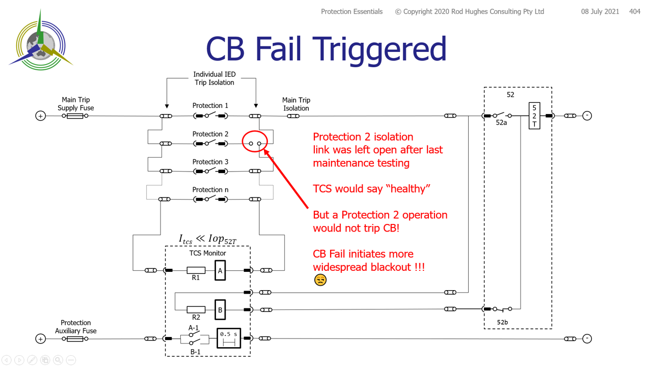
Hence the Re-Trip attempt is timed to occur just slightly after the expected operating time of the breaker - typically 40-100 milliseconds, but still well less than the typical CB Fail time of ~400 milliseconds. Note that the Re-Trip circuitry obviously has to bypass the main protection trip links all the way to the CB mechanism itself so that it is truly independent of any open circuit wiring in the main protection trip path. 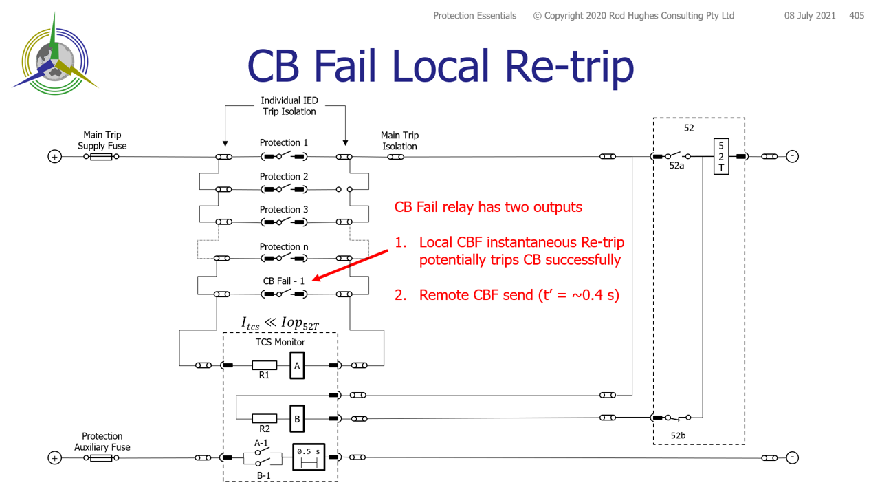 Image Modified Image Modified
|