Some have simply said that DISTANCE between the CT and the relay is THE sole criteria for selecting 1 A or 5 A rating - short runs of cable use 5 A, long runs use 1 A. In decades past, 5 A secondary CTs were basically THE choice for any protection or metering system. Then around the 1980's, that started to swing heavily to 1 A CTs. Why? Does it matter? ... I mean, you just buy relays and meters to suit ... or are there reasons for the preference now for 1 A CT secondary? Yes there is good reason so here is an explanation of that change. As we know, CT selection, at least P class, is all about Ohm's Law applied to the connected burden ... the maximum current we want to drive without saturation or loss of accuracy and the impedance of the wires plus the devices (we generally assume that the burdens are purely resistive). 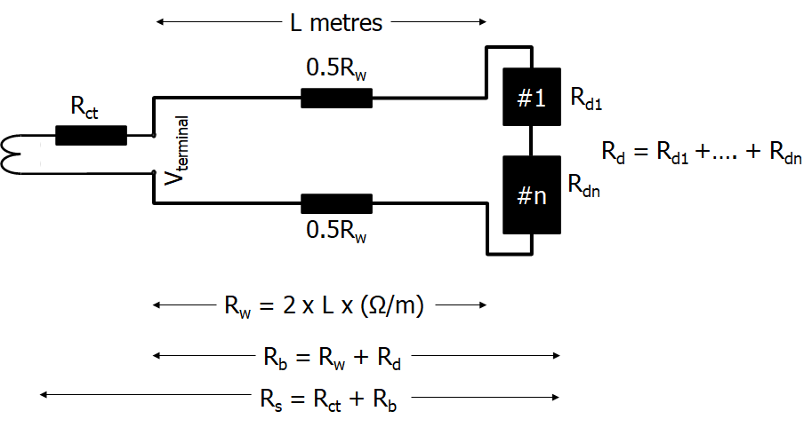
Applying Ohm's Law: Vterminal = ( Ipsc /(Ipr/Isr) ) x Rb
= ( Ipsc /kr ) x Rb
where IEC 61869 defines:
Ipsc = rated primary short circuit current ... i.e. maximum primary fault current ... e.g. 20 kA
Ipr = rated primary current ... e.g. 1000 A
Isr = rated secondary current ... e.g. 5 A or 1 A
Rs = secondary loop resistance Rs = Rct + Rb
Rb = rated resistive burden i.e. total resistance of wires and devices
kr = rated transformation ratio ... i.e. rated turns ratio ... e.g. 100/5 A = 200, 1000/1 A = 1000 For the purposes of this analysis, it is necessary to add the extra definitions:
Rw = resistance burden of the wire loop: CT-device(s)-CT = 2 x distance x Ohms/metre
Rd = resistance of the individual device(s) at the specific value of current. Although not absolutely true, we can assume here that Rd is the VA burden of the device divided by the square of the current at that burden.
Therefore Rb = Rw + Rd Therefore
Vterminal = ( Ipsc /kr ) x (Rw + Rd)
Some national Standards such as Australian Standard AS 1675 (long withdrawn in favour of adoption of International Standards IEC 60044 and now IEC 61869 series) specified the CT directly by the Terminal Voltage:
e.g. 1000/5 5P150 F20
Current ratio 1000/5
5% accuracy at 20x rated current
150 V terminal voltage capability at 20 x rated current
i.e. the maximum burden you could connect was 150 V / (20 x 5 A) = 1.5 Ohm However the IEC Standards are referenced on the rated burden
e.g. the IEC equivalent of the above CT is 1000/5 37.5 VA 5P20
Current ratio 1000/5
5% accuracy at 20x rated current
Maximum rated burden 37.5 VA (I² x R = 5² x 1.5) On the other hand if we choose 1 A secondary with the same connected burden - the specifications would be: e.g. 1000/1 5P30 F20
connected burden = 1.5 Ohm
Current ratio 1000/1
5% accuracy at 20x rated current
so terminal voltage capability at 20 x rated current = (20 x 1) x 1.5 = 30 V
1000/1 1.5 VA 5P20
connected burden = 1.5 Ohm
Current ratio 1000/1
5% accuracy at 20x rated current
so rated burden is now = 1² x 1.5 = 1.5 VA
That "looks" to be a much less capable CT with only 1.5 VA rated burden All four CT specifications yield the same performance. This still leaves us wondering why was the old practice so heavily in favour of 5 A? Obviously for the same primary current, a 1 A CT has 5x the number of turns.
1 A CT with 5x the number of turns means the Volt/Turn is lower for the same voltage requirement.
1 A CT with lower Volts/Turn means for the same voltage requirement means lower cross section area of the CT core ...
Sounds good. The answer is ... it depends on what we know about the burden! Burden affects the voltage requirement and that is definitely not the same for 1 A and 5 A CTs! We have assumed in the above that the burden is a "fixed" impedance regardless of setting and regardless of applied current, e.g. the impedance of copper wire is constant regardless of the magnitude of current (a least until it starts to melt!) so we need only to apply the length of the wire to the Ω/m of the particular size wire Rw = length x Ω/m Wire impedance is dependant on the cross sectional area of the wire as per this table | mm² | milliOhms/m | 200 m
loop |
|---|
| 1 | 18.1 | 3.62 Ω | | 1.5 | 12.1 | 2.42 Ω | | 2.5 | 7.41 | 1.482 Ω | | 4 | 4.61 | 0.922 Ω | | 6 | 3.08 | 0.616 Ω |
Hence 100 m of 2.5 mm² wire from a CT to the relay is 0.741 ohms, or a loop of two wires CT-relay-CT is 1.482 ohms That leaves us to consider the device burden. "In the good old days", what seems to be a simple function of an Inverse Definite Minimum Time relay is actually a complex burden that depends on the tap/plug setting and the multiple of the current to that setting.
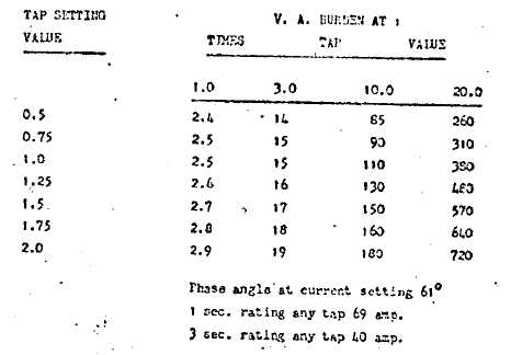
Sometimes you had to ask the vendor for their burden tables for the specific setting range .. e.g. for a GEC/Alstom CDG11 Standard Inverse curve relay for the common setting ranges: 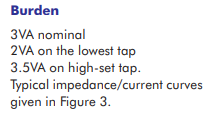
0.1 - 0.4 A EF 10-40% 1A | 0.5 - 2.0 A OC 50-200% 1A EF 10-40% 5A | 2.5 - 10 A
50-200% 5A |
|---|
| | 
"Figure 3" for a 2.5-10 A setting range
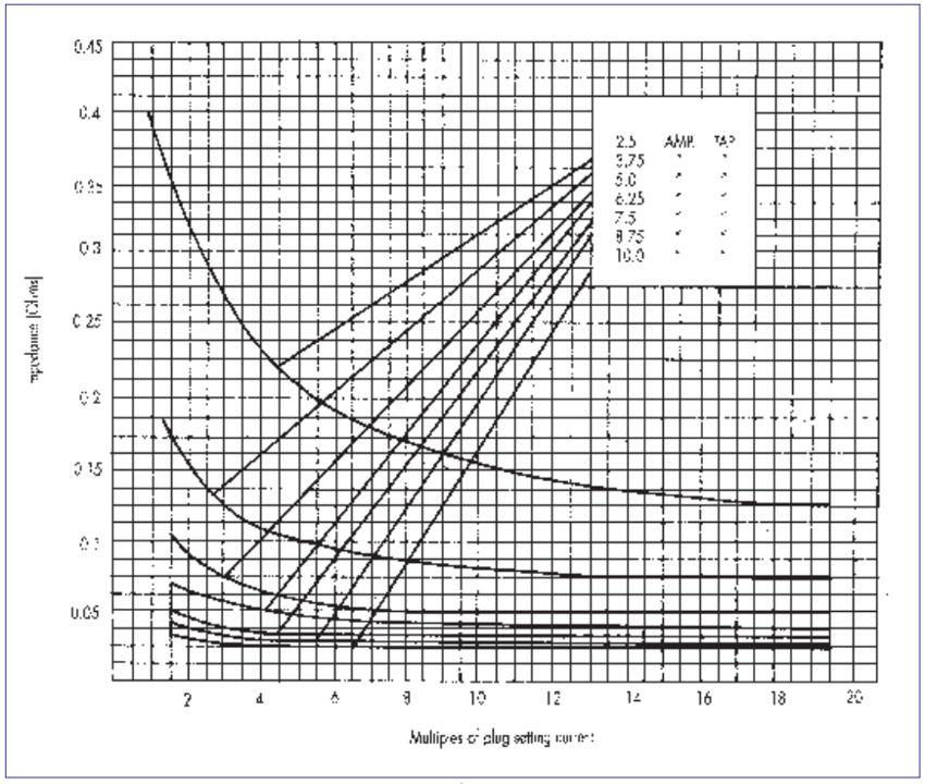 The graphical representation shows that
it is reasonable to assume the impedance
is constant above 20 x setting (as you
would expect as just the resistive
component of the saturated coil when
the disc cannot spin any faster) |
Other curve CDG relay burdens are shown in the PDF originally written by my first boss Ted Ransom available here: Applications Home You will note that these impedances shown in the tables above have "angle", but for simplicity of calculations for this presentation, I will assume they are purely resistive. What may surprise you is the large burden of the elements at high multiples of setting. Whilst nominally 3 VA at setting, at 20 x setting current these changed considerably
0.1-0.4 A element 20x the lowest setting of 0.1 A is 250 VA (62.5 Ω) and at 20 x the highest setting 0.4 A it is 680 VA (10.625 Ω)
0.5-2 A element at 20 x the lowest setting of 0.5 A is 260 VA (2.6 Ω) and at 20 x the highest setting 2.0 A it is 720 VA (0.45 Ω)
2.5-10 A element at 20 x the lowest setting of 2.5 A is 320 VA (0.128 Ω)and at 20 x the highest setting 10 A it is 960 VA (0.024Ω) It is also necessary to remember that the tables only show up to 20 x setting. However for solidly earthed transformer systems, the maximum fault current phase-phase or phase-earth is probably going to be somewhere between 10 and 20x rated current.
That maximum fault current would therefore be 200 x the 10% earth fault setting, and yet we still need accuracy to be retained .. i.e. we do not want the CT to saturate! It is these impedances that meant that the first generation of electronic test sets in the 1980's had a hard time testing earth fault relays in particular! Why are there such high impedances in electromechanical IDMT relays?
Well, the coil of the CDG11 et alia is a complex seven co-wound strands of wire layers in order to get even flux distribution for all selected taps.
Plus at low settings such as 0.1 A, to get the same Ampere.Turns "energy" generating the turning force on the disc as a 10 A setting would generate, you needed 100 x the number of turns.
As the number of turns increases with lower setting, you need to use smaller size wire to fit them onto the same core.
More turns means longer length of finer and higher impedance wire.
And finally because it is IDMT, nothing is linear and there is a natural phenomena which I will simply call "saturation" of the relay magnetic core which reflects in the flattening of the apparent impedance of the coil at larger currents.
True elegance in design .. you have to admire the engineers of "a century ago" imagining how all these flux interactions can work to create a rotating disc for an IDMT relay or a rotating disc energy meter! Ohm's Law allows us to determine the terminal voltage at the CT as:
Vterminal = ( Ipsc /kr ) x (Rw + Ref + Roc) We also know that any winding is governed by the formula E = 4.44 f A B N
E is the rms voltage developed "internally" to the CT. E = Vterminal + (Ioutput x Rct)
f = frequency
A = cross section area of the core
B = flux density
N = number of turns From that we derive <<Volts per Turn E/N>> is proportional to <<cross section x flux density AB>> So now lets apply all that to the choice of 5 A rated CT vs 1 A. As said earlier, CT is all about Ohms Law and the maximum terminal voltage at the maximum current in the connected burden.
Here is an example where an earth fault has occurred and hence current is flowing through both the Earth Fault element and one of the Over Current elements.
The relays are 100 metres from the CT, i.e. total length of the two wires carrying the current is 200m.
The wires are 2.5 mm²
The CTs are 1000/5 A.
CDG11 EF setting range 10-40% i.e. 0.5-2 A, with a tap setting of 10% i.e. 0.5 A (Note there are other application difficulties associated with a 10% EF setting which usually drives a more practical lowest setting of 20%).
CDG11 OC setting range 50-200% i.e. 2.5-10 A, with a tap setting of 100% i.e. 5 A 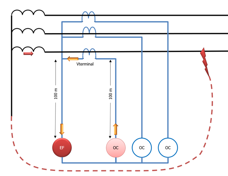
Using the relay impedance tables we can derive the operating conditions summarised as follows. We would need a CT that is capable of producing minimum 414 V at 20 x rated current,
i.e. using next highest standard ratings: AS 1675: 1000/5 10P414 F20 or IEC 61869-2 1000/5 104 VA 5P20 CT Turns ratio 200 | Applied Current
Ifmax 100 A
20 x Rated
200 x EF setting
20 x OC setting |
|---|
| EF element VA @ Applied Current | 26000 VA | | EF Impedance @ Applied Current | 2.60 Ω | | OC element VA @ Applied Current | 520 VA | | OC Impedance @ Applied Current | 0.05 Ω | | Loop Impedance | 1.48 Ω | | Total CT burden Ohms | 4.13 Ω | CT Terminal Voltage
(Kneepoint voltage Ek > Vterminal)
| 414 V | Volts/Turn
(proportional to x-section area) | 2.0700 | | CT VA | 41340 VA | | Min IEC Rated Burden | 103.35 |
If the relay was only five metres from the CT, we would only require AS 1675: 1000/5 10P273 F20 or IEC 61869-2 1000/5 69 VA 5P20 Using the same system parameters as above, but change to a 1 A rated CT, the summary is AS 1675: 1000/5 10P1299 F20 or IEC 61869-2 1000/5 65 VA 5P20 CT Turns ratio 1000 | Applied Current
Ifmax 20.0 A
20 x Rated
200 x EF setting
20 x OC setting | relative to
table for
5 A CT |
|---|
| EF element VA @ Applied Current | 25000 VA |
| | EF Impedance @ Applied Current | 62.50 Ω |
| | OC element VA @ Applied Current | 380 VA |
| | OC Impedance @ Applied Current | 0.95 Ω |
| | Loop Impedance | 1.48 Ω |
| | Total CT burden Ohms | 64.93 Ω | 15.7 x | CT Terminal Voltage
(Ek > Vterminal) | 1299 V | 3.13 x | Volts/Turn
(proportional to x-section area) | 1.2990 | 0.62 x | | CT VA | 25973 VA | 0.62 x | | Min IEC Rated Burden | 65 VA | 0.62 x |
If the relay was only 5 m from the CT, AS 1675: 1000/5 10P1271 F20 or IEC 61869-2 1000/5 64 VA 5P20, i.e. basically no difference whether 100 metres or 5 metres between the relay and the CT because of the dominance of the EF element impedance.
Distance CT to CDG
2.5 mm² wire | 100 m | 5 m | | Ratio | 1000/5 A | 1000/1 A | 1000/5 A | 1000/1 A |
|---|
| Ek >414
Volt/Turn>2.07 | Ek >1299
Volt/Turn>1.299 | Ek >414
Volt/Turn>1.365 | Ek>1271
Volt/Turn>1.271 | | minimum AS 1675: | 10P414 F20 | 10P1299 F20 | 10P273 F20 | 10P1271 F20 | | minimum IEC 61869-2: | 104 VA 5P20 | 65 VA 5P20 | 69 VA 5P20 | 64 VA 5P20 |
| Note |
|---|
| as can be seen, a 1 A CT with electromechanical induction disc relay elements requires a much higher CT terminal voltage than a 5 A CT,
... which also means a much larger Kneepoint voltage than for a 5A CT The 1 A CT has 5 x the number of turns than a 5 A CT, hence total wire length is 5 x longer taking 5 x the time to wind the coil (with respective cost implication of material and time).
,... and due to physical limitations of the core and window, probably much finer wire is also used and hence a higher CT winding resistance if you wanted to convert to a PX class CT specification even further increasing minimum kneepoint to achieve the terminal voltage. The offset is we actually get a reduction in CT core cross-section area so potentially ironically (pun intended) less core iron than a 5 A CT So .. "in the good old days", 5 A CTs were far more common. |
The MCGGx1 series released ~1980/81 was a revolution in overcurrent protection with its microprocessor functionality using a Log-table lookup mechanism.
By mid 1980's it was replaced with a different microprocessor as the MCGGx2 series. MCGG 22 single element relay burden is:
1 A ... <0.25 Ohm regardless of setting and regardless of applied current
5 A ... <0.02 Ohm regardless of setting and regardless of applied current 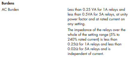
MCGG22 5 A EF relay, 10% setting at 20 x rated current is 0.02 ohm
MCGG22 5 A OC relay, 100% setting at 20 x rated current is 0.02 ohm
200 m 2.5mm2 1.482 Ohm
Total connected burden 1.522 Ohm
CT Terminal voltage @ 100 A 152 V For 1000 m between CT and relay: minimum CT is AS 1675: 1000/5 10P152.2 F20 or IEC 61869-2 1000/5 75 VA 5P20
c.f. the above analysis CDG11 10% EF, 100% OC: minimum CT is AS 1675: 1000/5 10P414 F20 or IEC 61869-2 1000/5 75 VA 5P20 For 5 m between CT and relay: MCGG22 1 A EF relay, 10% setting at 20 x rated current 0.25 ohm
MCGG22 1 A OC relay, 100% setting at 20 x rated current 0.25 ohm
200 m 2.5mm2 1.482 Ohm
Total connected burden 1.982 Ohm
CT Terminal voltage @ 20 A 39.64 V Clearly the 1 A CT has lower terminal voltage, lower kneepoint, lower cross section area of CT core Distance CT to MCGG
2.5 mm² wire | 100 m | 5 m | | Ratio | 1000/5 A | 1000/1 A | 1000/5 A | 1000/1 A |
|---|
| Ek >153
Volt/Turn>0.765 | Ek >31
Volt/Turn>0.031 | Ek >12
Volt/Turn>0.06 | Ek >3
Volt/Turn>0.003 | | minimum AS 1675: | 10P153 F20 | 10P31 F20 | 10P12 F20 | 10P3 F20 | | minimum IEC 61869-2: | 39 VA 5P20 | 2 VA 5P20 | 3 VA 5P20 | 1 VA 5P20 |
CT specification as demonstrated above is a simple application of Ohm's Law, so we can "reverse" the question to be whether or not a particular VA rating CT could be used in different applications. The reference is a 1000 A rated primary. We also have different applications of 5 m, 20 m, 30 m, or 100 m between the relay and CT (double that length as loop) In this example, the MCGG22 relay is again used which has a fixed burden regardless of rated current or magnitude of current, but different for 1 A vs 5 A rated relay In deciding if a 10 VA or a 20 VA rated P class CT is sufficient, we also have to consider the choice of different cable sizes of 2.5 mm², 4.0 mm², 6.0 mm² or 10.0 mm² Click the expansion links to see the calculation tables. The conclusion is that BOTH 1 A and 5 A rated CTs can be used for long cable runs ... it is "just" a question of what VA rating you specify to satisfy Ohm's Law.
| Expand |
|---|
| title | 10.0 mm² cable, with a 10 VA rated 1 or 5 A CT is OK even for the 100 m distance |
|---|
| There are no negative results in the bottom two rows. 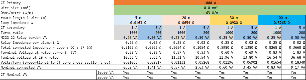
|
| Expand |
|---|
| title | 6.0 mm² cable100 m long, 10 VA 1 A CT is OK, but you could NOT use a 10 VA 5 A CT. 20 VA 5 A is fine |
|---|
| Only a 5 A CT with 10 VA rating would not be suitable for up to 100 m cable run. 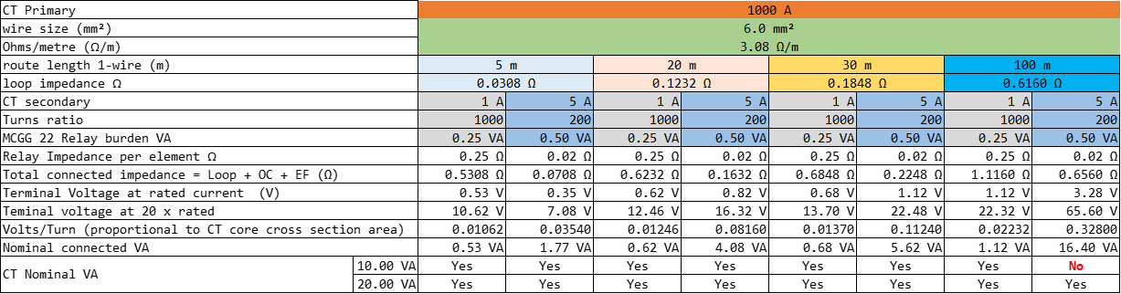
|
| Expand |
|---|
| title | 4.0 mm² cable, even a 20 VA rated 5 A CT would not suit 100 m distance, but a 10 VA 1 A CT would be OK |
|---|
| Neither 10 VA or 20 VA rated 5 A CT would suit 100 m cable run. You would just need to specify at least 25 VA. Even just 10 VA 1 A CTs would be OK 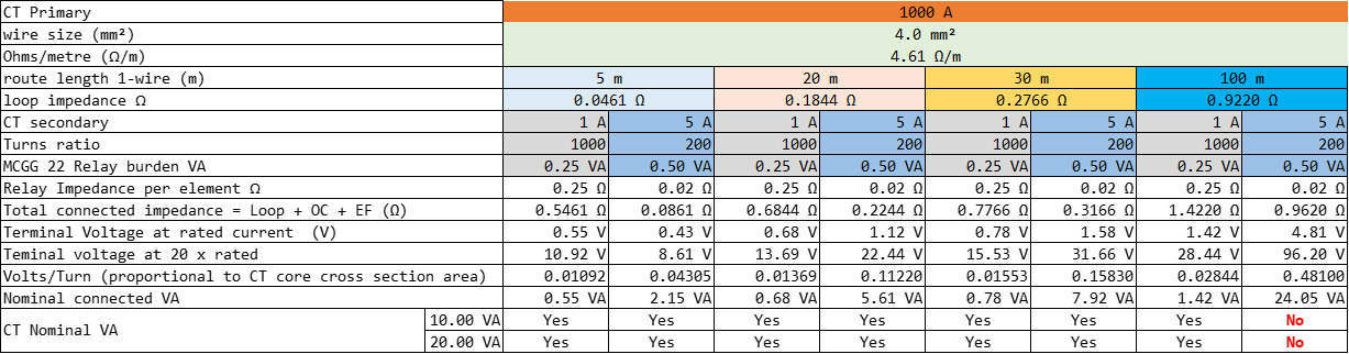
|
| Expand |
|---|
| title | 2.5 mm² cable 30 m long, 20 VA 5 A would work fine, but a 10 VA 5 A would not. 30 m with 10 VA 1 A CT would be OK. 100 m 5 A requires 40 VA |
|---|
| This size cable will mean a 5 A rated 10 VA CT will not suffice, but 20 VA would be fine. 10 VA 1 A CT would also suffice even for 100 m. 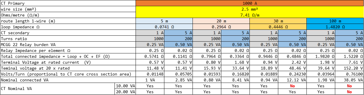
|
| 
