As I write this page, some Parts of IEC 61850 are already 18 years old.
Some Parts have just achieved release of Edition 2.1, some are available as Edition 2, some are just emerging as Edition1 1, and yet other Parts are still in first draft.
Yet in all of this, the basic principles of what IEC 61850 has been achieving have remained the same. The newer Editions are just recognising the ever broadening range of applications that we are increasingly choosing to apply it to. As I have often said … “IEC 61850 is an enabler technology!”
The more we do “this”, the more we realise it can also do “that”!
I also qualify that “enabling” with a warning : “Just because we can doesn’t mean we should!”
We have a professional obligation to understand the context of what we are about to do and on what basis we are about to do it.
As my good friend Alex Apostolov always says we must start with three fundamental questions to be answered: What are we doing?
Why are we doing it?
How are we doing it?
As such an enabler technology, where is this leading us? What will it allow us to achieve, if not now, but in the years/decades to come as we develop our levels of acceptance and use of the technology? We don’t want what we do now to be obsolete in a few years’ time when we think of something new we want to achieve and implement. We want our legacy to the future projects be that our work is seen as positive “stepping stones” and “building blocks” rather than needing a total reversal of direction. I have a favourite "Hagar" cartoon I refer to for such matters - it was actually published in CIGRE Technical Brochure 326 "Introduction of IEC 61850 and its impact on protection and automation within substations" (https://e-cigre.org/) 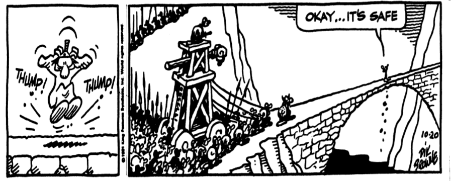
I suggest that this is implying we must do at least three things: - Leverage experience
- Seek power engineering context
- Integrate specialist domain expertise: Protection, SCADA, Primary … IT
One aspect of new possibilities as a result of new technology implementations is how we deploy digital technology. It raises a very good question: How “digital” is digital? Certainly there have been many investigations and trials as reported over several CIGRE events from as far back as the 2007 SC B5 Colloquium in Madrid. I recall a very interesting (ahead of its time innovative) presentation by a good friend of mine, Janez Zakonjsek. The presentation firstly described the evolution of extracting the Analogue‑to‑Digital converter modules from the multiple relays and using the LAN to communicate the Sampled Values to the IEDs exactly as the Standard proposes. But the really interesting aspect was that Janez posed the suggestion that given we are now deploying a box of electronics at the sensor head and sending the SV to the control room for processing, why not put all the processing in the same box as the MU and just send the outcome of the processing as GOOSE to wherever it needs to go, and of course still publish its SV stream in case some other bay needs that information as well.
Yes, the MU box once again looks like a relay more or less as we know it now with sensor inputs and a LAN connection, just located out near the sensors.
No more specific need for a protection panel and separate IEDs!
Food for thought … In the meantime, many are already considering the physical IED requirements in the sense of the so‑called “ONE BOX SOLUTION”. It is not really just one box as there are many additional boxes as sensor inputs and physical I/O interfaces.
The “one box” is referring to incorporating all the automation (protection, control, metering) functions into a single box rather than having multiple boxes providing specific functions for their respective primary plant as the generator, motor, transformer, busbar, feeder, cap bank …. So it is worthwhile considering the “how digital is digital” question in the context of what I pose as four generations of digital substations 1. Station Bus GOOSE/MMS only with wire-based I/O to primary plant.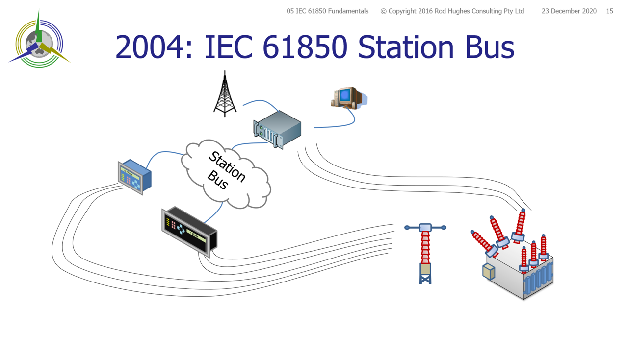
This has been widely deployed in various degrees and various engineering processes (top‑down vs bottom‑bottom) since 2004.
It can be argued under the “pure” definition of Process Bus that the protection relays are providing the primary plant interface function with wires connecting to the primary plant e.g. SCADA MMS carries the CB Status and CB controls and hence a “form” of limited Process Bus already exists.
However I would suggest the intended meaning of Process Bus is a LAN port and d.c. auxiliary supply as the only connections to the primary plant itself. 2. Station Bus GOOSE/MMS + Process Bus GOOSE/MMS messages to “intelligent LAN‑connected” primary plant directly or via a Remote I/O unit.It could be said that this has had limited deployment as whilst the LAN interfaces to the primary plant (direct or RIO) eliminates wires, the CT/VT and other sensors remained all wire‑based with inherent legacy engineering problems. After all, IEC 61850 is an advanced engineering process that eliminates all the problems of wire-based engineering. 3. “Distributed Digital Substation” = Station Bus GOOSE/MMS + Process Bus GOOSE/MMS/SV with “functionally segregated” IEDs.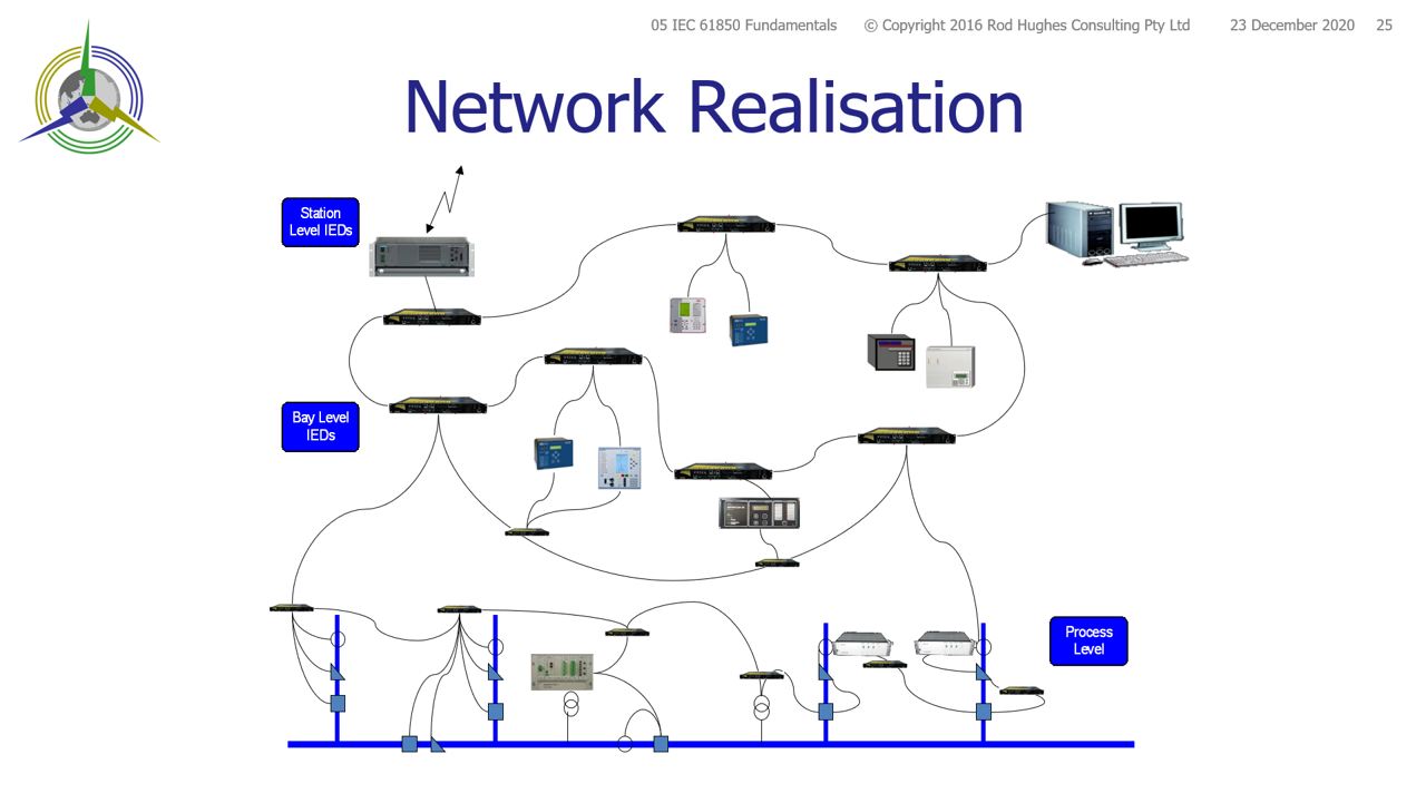
This is in the full spirit of the official Purpose of the Standard as stated in IEC 61850‑1 Section 4 para 4 : The purpose of the Standard is neither to standardise (nor limit in any way) the functions involved in substation operation nor their allocation within the Power Utility Automation System
That last parts says it does not matter if you have 10 boxes providing the required functionality or 100 boxes as long as they can be [easily] configured to communicate correctly with each other.
It is also the basis of separating the A/D conversion of sensor signals into Merging Units and both A/D and D/A conversion into Remote I/O IEDs. Over the last few years we have seen the move from trial substations using Merging Units to full standard utility implementation.
As I have been demonstrating in my training courses since 2010 as would be the case, utilities are reporting some 30% savings in the cost of the substation – yes, I said substation, not just the secondary system. the The one function I believe is sadly lacking, or in extremely limited supply, is that there is really only one generally available grid level revenue class 0.2S metering solution with IEC 61850 Sampled Value inputs.
I include the Standards bodies in that call to update their grid metering Standards to cater for certification of distributed‑LAN‑connected IED solutions as an alternative to the conventional meter. 4. "Centralised Digital Substation” = Limited Station Bus with “1‑central‑box” IED and Process Bus GOOSE/MMS/SV.I am proud to say that this "possibility" is something that I have been "putting out there" in my training courses since 2008. 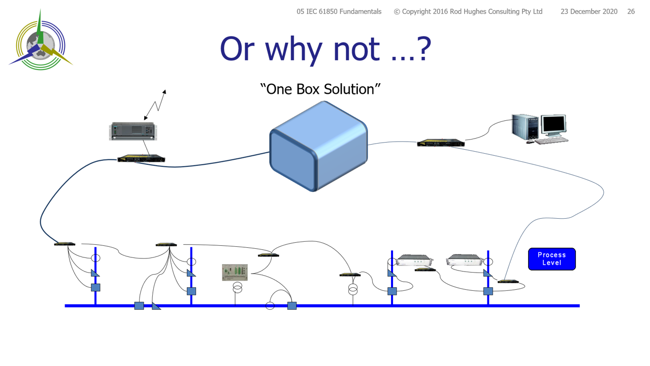 The bay-to-bay GOOSE messaging is no longer via the substation LAN - it is all within the 1-box. Station Bus only applies to the SCADA Gateway and substation HMI
This also is in the spirit of the Purpose of IEC 61850.
No criticism, but clearly this is in the interests of a single vendor, or perhaps two vendors each supplying one of the duplicated “1-box” system to satisfy redundancy. There are certainly at least a few things to consider for these “1‑box” solutions. 4.1 Network bandwidthAs a 1‑box solution, you have to consider bandwidth as a starting point. Ignoring GOOSE and MMS bandwidth, a 100 Mb/s comms port can only support upto 12 Merging Unit streams in the network (~8 Mb/s per stream) being allowed to arrive at the IED. This can be achieved by using VLANs and/or Multicast Filters at the switch ports. Hence if Busbar protection is being implemented, some difficulties will quickly arise by the time you have several CT Merging Units and a couple of other voltage MUs. Obviously one option is for the IED to have multiple 100 Mb/s ports which need some special configuration of the switches and the IED ports to get the right messages on the right ports. Or the IED and switch ports must support 1 Gb/s or even higher. This is arguably much easier/common place with the SFP plugin modules, but don’t forget the backbone between the switches should probably then be considered as well, perhaps even 10 Gb/s. 4.2 Testing regimeA 1‑box device is going to have hundreds of individual Logical Nodes.
Each will need to be tested, possibly individually whilst all the other LNs are “in service”.
OK, you have duplicate 1-box systems so that you are not totally without protection whilst the other system has one or more “Functions Under Test” (FUT) or the complete “Device Under Test” (DUT). Some grid codes allow the system to be operated without effective protection redundancy for up to 8 hours. However the test arrangements require all the other IEDs to be set in the appropriate operating mode to make sure they correctly respond to “live” system signals and also correctly respond differently to signals from FUT. The IEC 61850‑7‑4 has provided the necessary test mechanisms in the <<.Beh>> and <<.Mod>> settings which was expanded in Edition 2. Sadly, so many implementations have ignored all that and developed (a plethora of) proprietary vendor‑ or owner‑specific “isolation mechanisms”. A slight anomaly exists now in that most IEC 61850 test processes require the availability of the individual FUT output results to be available on the LAN so the test set can detect the result of the various signal injections.
In the above 3rd generation systems, this is arguably already the existing configuration of all the IEDs, or at least only that particular DUT needs to have temporary datasets created to support the testing program.
However these 4th generation 1-box solutions have hundreds of available LNs and thousands of individual Data Objects that may need to be communicated to the test set. 4.3 Firmware upgrades (bug fixes)I think it is fair to say the power industry “hates” IED upgrades of hardware or firmware. I have had the duty to manage such processes on behalf of both vendor and asset owner on several occasions as critical “must do” changes – they are difficult to schedule, difficult to do, time consuming and costly.
Manufacturers of in‑principle “single” function devices (an overcurrent relay, a distance relay etc) go to great effort in testing firmware changes sometimes taking in excess of three months in the simulation labs testing thousands of test scenarios to prove “non-regression” that this fix doesn’t create some other problem.
The asset owners are then faced with planning for taking one IED out of service, possibly reconfiguring the power system to allow for the time to undertake the upgrade and carry out testing. Now consider this in a 1-box environment. The manufacturer is faced with a plethora of non-regression testing to prove teh thousands of functions are not impaired by one small bug fix - if it took say three montsh for "single function" IEDs, teh full test across combined functions will be significant, potentially delaying critical bug‑fix availability. For the asset owner, That X or Y protection system for all bays and protection, control and metering functions are taken out of service simulatneously. Then you are faced with testing of ALL bays that they are operating properly with all the right signal exchanges. 4.4 ReliabilityAnother subtle consideration for 1‑box protection solutions is reliability.
Reliability has two sides of the same coin – DEPENDABILITY and SECURITY. We generally deploy “parallel” duplicate/redundant X and Y systems to ensure high DEPENDABILITY – either system will cause the CB to trip when it is essential that it must trip.
Refer the Availability analysis of duplicate IEC 61850 based systems Reliability, Dependability, Security, MTBF, MTTR, Availability Security on the other hand is potentially compromised by redundant systems.
With the systems now relying so heavily on signals between functions, we must also ensure that the CB WILL NOT trip when it should not.
A missing or delayed signal between functions can cause another function to adversely operate when it should not!
Duplicated systems effectively means that there is twice as much possibility that a single failure could lead to a system operation with inadvertent/unwanted circuit breaker tripping. Hence since PRP/HSR became available, we have enjoyed the possibility of ensuring SECURITY by providing bumpless operation of the system. Now .. consider a 1-box solution. Yes there may well be PRP/HSR systems for connection between the MUs and RIOs to the other IEDs. But within this 1-box system, the entre substation SECURITY is based on the correct internal operation of the IED to provide the necessary signals between all the functions.
OK, that is always the case with any IED, however we are now applying that same reliance not just to one form of protection in the facility (the individual IEDs providing protection for the generator, motor, transformer, busbar, feeder, cap bank ….), but for ALL the combined such functions operating within the one IED. Again we need to consider what that means within the IED. Essentially all these functions are “just” algorithms running on the one microprocessor. Since we have been “happy” to accept multiple functions on one microprocessor to work correctly since the first days of such in the early 1980’s, we have no reason to believe that a significant increase to the number of such functions on the one microprocessor would suddenly not be able to work correctly .. or at least we would expect the vendor to put in enough “horsepower” to the microprocessor and memory selection to make sure it will work correctly. 4.5 ResilienceIt is clear that the release of IEC 62439-3 PRP and HSR mechanisms has been an ESSENTIAL part of ensuring RELIABLE operation of protection systems. If that one central microprocessor fails, ALL functions in that 1-box system fail.
Your ENTIRE substation now only has ONE protection system, no redundancy!
The ONLY solution is a complete IED replacement as quickly as possible.
Your first thought is of course likely to be the time for appropriate technicians to get to site, time to install the new IED, and the time to test the ENTIRE substation’s set of functions operating on that one IED. So HERE is the REAL benefit of digital substations (3rd or 4th generation). Given that ALL signals are LAN based (or within the IED itself), should one IED start “smoking” it can be “replaced” by another IED that is already powered up and connected to the LAN – a hot-standby spare IED. As stated in my CIGRE contributions My Papers and Contributions reference RH19D and RH19P, even at “3 am in the morning”, a technician from their “living room” could reconfigure the hot-standby spare IED to assume the live operating status all within 5-minutes.
This hot-standby spare IED can be pre-loaded with the same configuration as the live IED, or the technician can remotely load the CID associated with the "live" IED into the hot-standby spare IED and the system is back up and running exactly as it was. In 3rd generation substations, this just means having one hot-standby IED for each type of IED in the system. However, in 4th generation substations this means installing four (expensive) 1-box IEDs: - a live X IED
- a spare X IED
- a live Y IED
- a spare Y IED
|