| Section | ||||||||||
|---|---|---|---|---|---|---|---|---|---|---|
|
...
| Section | ||||||||||||||||||||||||||||||||||||||||||||||||||||||||||
|---|---|---|---|---|---|---|---|---|---|---|---|---|---|---|---|---|---|---|---|---|---|---|---|---|---|---|---|---|---|---|---|---|---|---|---|---|---|---|---|---|---|---|---|---|---|---|---|---|---|---|---|---|---|---|---|---|---|---|
However if you are using Sampled Values (IEC 61850-9-2), THEN you MUST have better than 1microsecond COHERENCY of time synch across all Merging Units so you really MUST use IEEE 1588 v2 PTP. As far as SV is concerned, it doesn't matter how the relay is synchronised as they use the SV Sequence Number to time align the SV messages based on the counters all starting from 1 within microsecond of each other and reset and start all over again at the start of the next 1-second window. I emphasise COHERENCY of time synch as SV doesn't actually need to know the actual time - just that every MU starts its 1-second window of sequence counter at exactly the same instant. Consider MU1 starting its Sample counter at 1 Counter at 0 at time yyyymmddhhmmss:xxx, .... but MU2 doesn't start its counter at 1 until 0.5 ms 0 until one millisecond later.
Yes, various time synch systems can give reasonably accurate time stamping from a centralised clock source. But the biggest problem is the latency in getting that time sync from the master clock through to the MUs ... all having adjusted for the latency between source and each individual MU. Latency correction through a LAN network is dealt with by LAN switches and end devices supporting IEEE1588 Precision Time Protocol (PTP) v2. PTP involves selection of different types of clocks and different modes within those clocks - clocks being required to be part of ALL the LAN switches to make it work.
PTP has means to identify the latency of the synchronising message from one clock to the next, and therefore can maintain coherency at the end target Merging Units. Time synchronisation for Sampled Values is further discussed on this page: What does time synchronisation mean for Sampled Values? PTP involves selection of different types of clocks and different modes within those clocks - clocks being required to be part of ALL the LAN switches to make it work. Grand Master Clock
Anchor |
|


| IED | IED's current time |
|---|---|
| Pub1 | 2016-12-22 14:42:33:432 |
| Pub2 | 2017-01-22 09:08:05:234 |
| Sub1 | 2015-03-58 18:28:15:010 |
So Sub1 would see the two messages arrive based on its own time stamp, but the <<T>> of the PDU header from Pub1 and its <<.t>> in its dataset will be both VERY different to the <<T>> and <<.t>> in the message from Pub2.
Hence in considering what time things happen, we first have to ask "do all IEDs have the same understanding (synchronisation) of what the current time is"!
The only "absolute" is that Sub1 knows the time it received each of the messages based on its own time clock.
So what does this mean when we want to do some debugging of GOOSE in FAT/SAT/Commissioning/Maintenance where technicians and engineers are trying to sort out why something happened at the GOOSE level – when did a publisher IED see an event vs another IED vs when did a subscriber know about it from receiving GOOSE??? This then comes down to how well the dataset has been constructed by the IED Vendor (if it is fixed dataset) or by the Systems Integrator or by the Tester. If well-constructed, you can analyse the datasets to extract the <<.t>> Data Attribute time stamps as the basis for Sequence of Events .. of course assuming all IEDs are appropriately time synchronised.
| Anchor | ||||
|---|---|---|---|---|
|
all MUs must be precisely synchronised to start each 1-second window within 1 microsecond of each other, i.e. 1 microsecond COHERENCY.
We don’t care even what year it is saying the date/time is but we MUST start each 1-second window with 1 microsecond COHERENCY.
…. otherwise the samples appear all skewed
Consider a current differential application using two Merging Units:
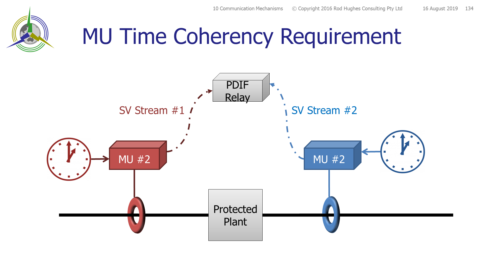
Other than for transformer differential applications, clearly the current flowing through the red sensor (be it conventional or non conventional instrument transformer) is the same as the current flowing through the blue sensor.
Therefore the relay should see the exact same waveform presented by each Merging Unit.
The samples captured by each Merging Unit at each instant are contained in the Sampled Values dataset being published by each Merging Unit.
At each instant of sampling, the merging Unit tags the samples with a counter <<seqNum>> which represents the "nth" sample within the 1-second sampling window, i..e at a sampling rate of 4000 Hz, the counter will increment from 1 to a maximum of 4000 every 0.025 milliseconds. At the start of the next 1-second window, the value of <<seqNum>> resets to a value of 1, and starts incrementing again.
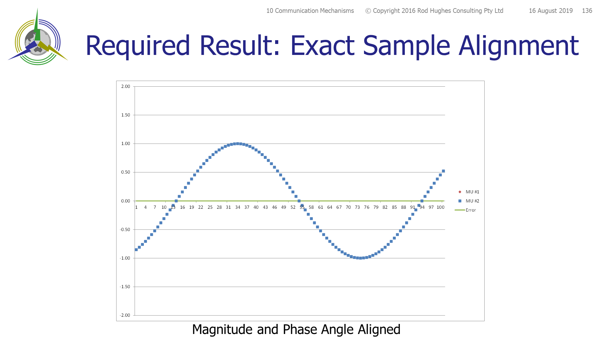 No error
In the example above each Merging Unit has its own independent clock and therefore there is no inherent time synchronisation between the two clocks, hence their 1-second windows will start at a different instant in real time.
A common time synchronisation mechanism in substations for SCADA Sequence Of Events log purposes has been the IRIG-B or 1 Pulse Per Second signal, generally distributed over coaxial cable.
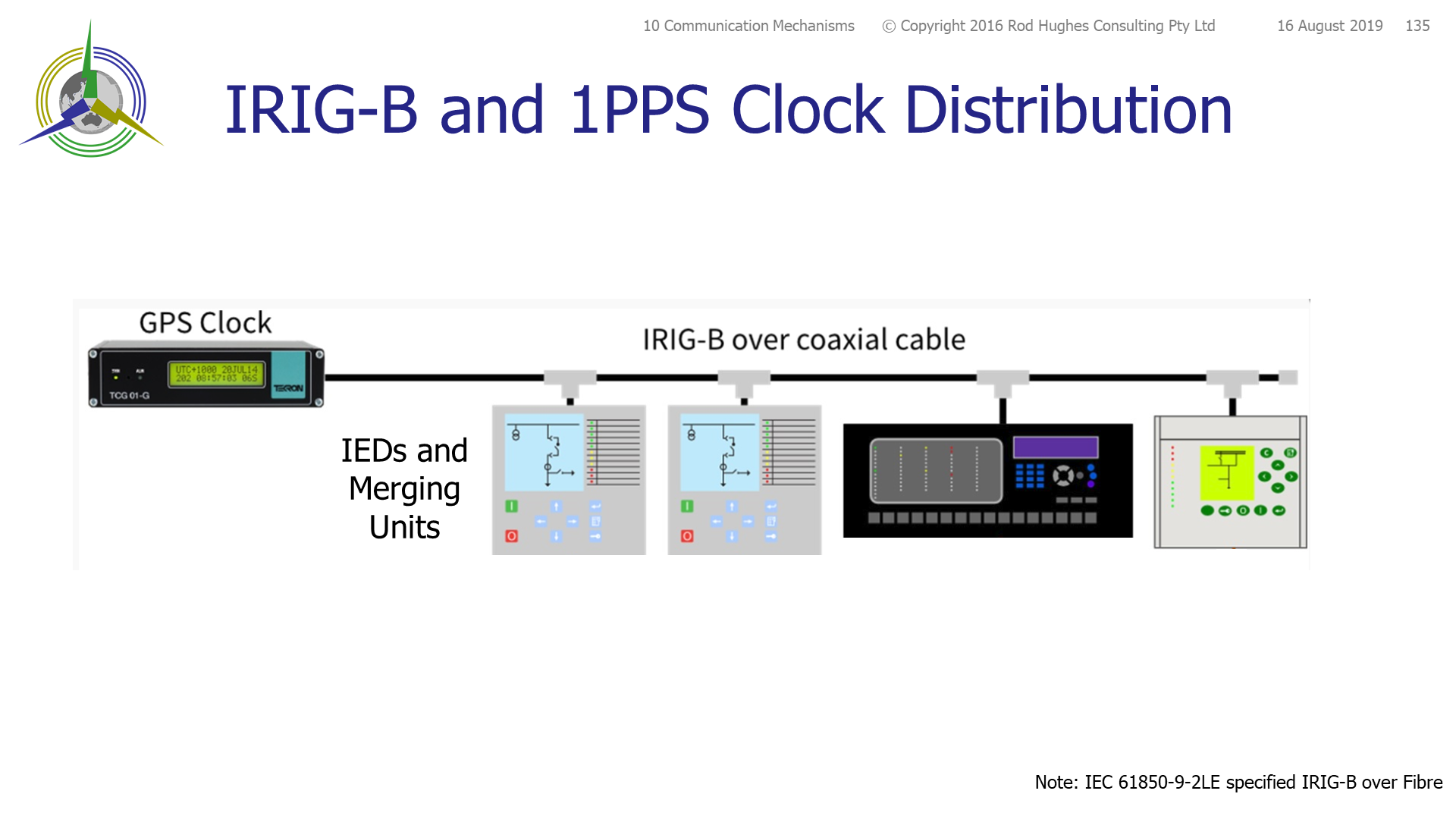
The overall length of the coaxial cable path means there is a real time difference between the synchronisation of the first IED and that of the last IED in the loop due to the path latency. In general this means their is a spread of time across the IEDs but will generally within about one millisecond accuracy time stamp.
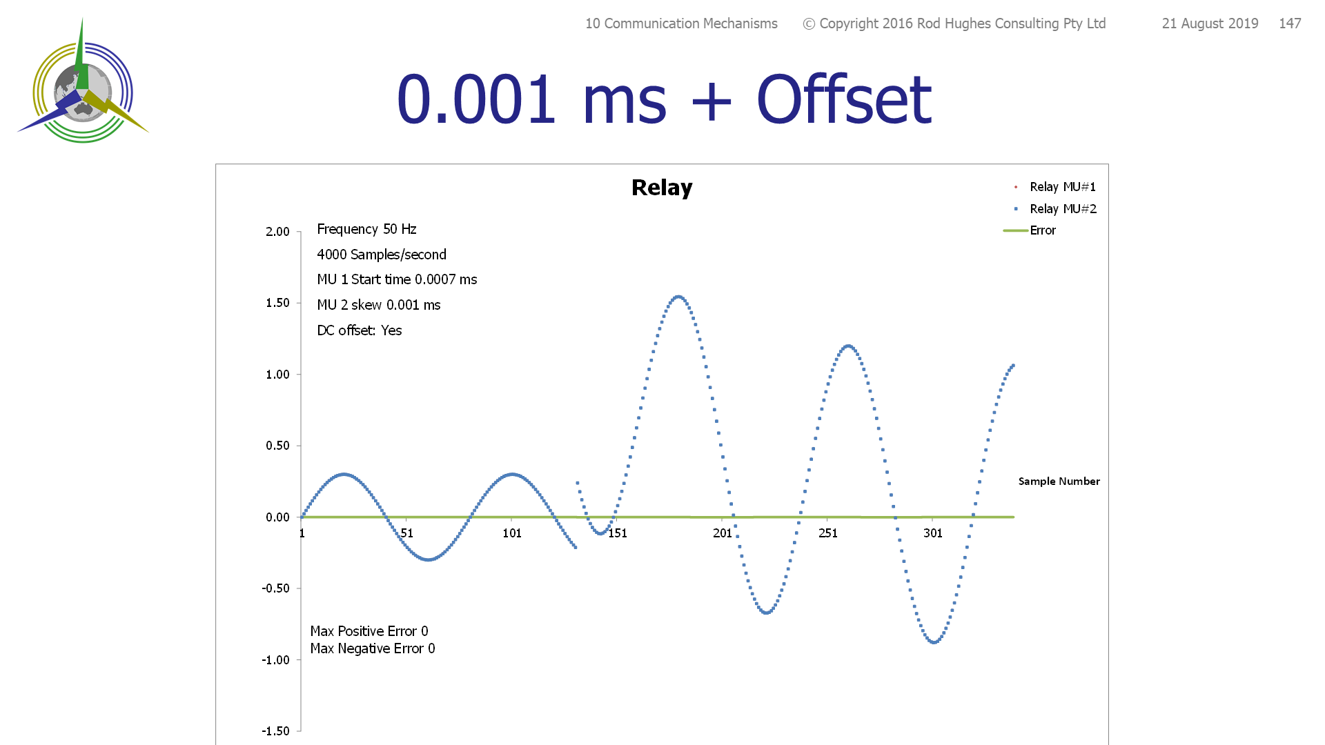
We can now consider what effect a one, five and 10 millisecond difference in the start of the 1-second window means to differential relays in particular, or indeed any relay which is using two or more sets of Sampled Value streams:
Use case 50 Hz, 4000 Hz sampling, DC offset at fault inception.
Four results are provided:
- one microsecond skew of 1-second window start
- one millisecond skew of 1-second window start
- 5.54 millisecond skew of 1-second window start
- 10 millisecond skew of 1-second window start
No noticeable |
Phase angle error |
Phase angle error |
Phase angle error |
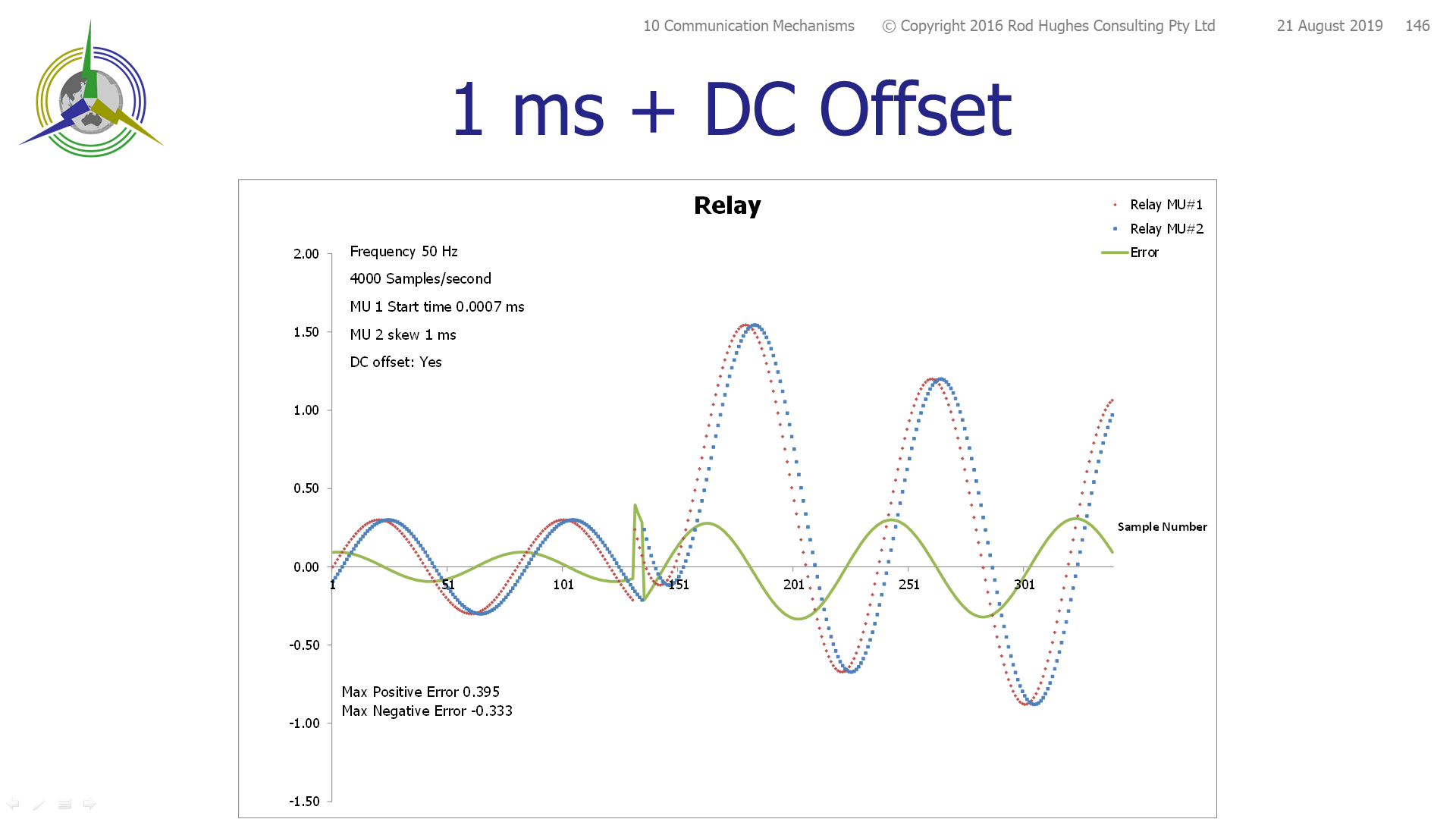
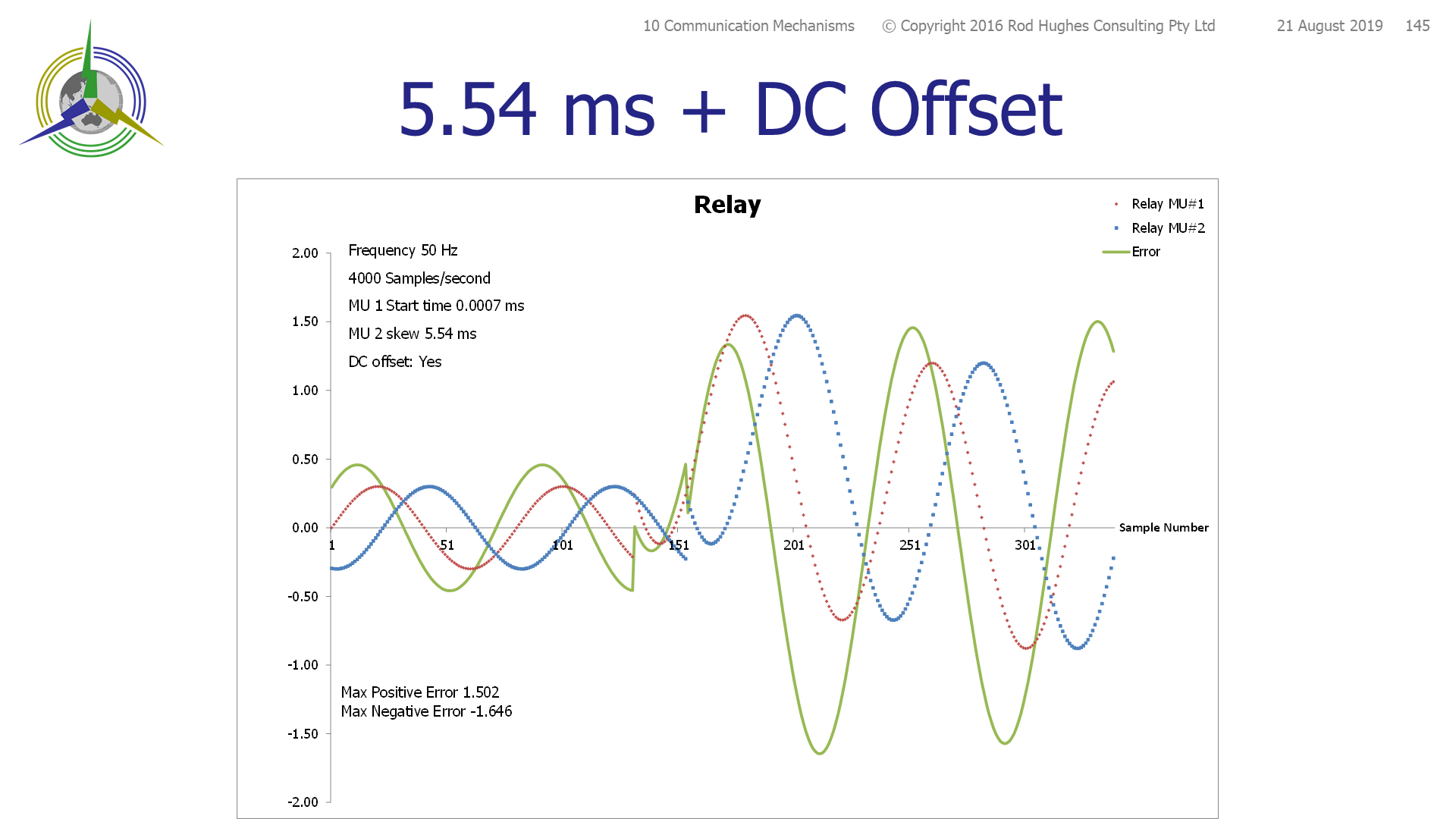
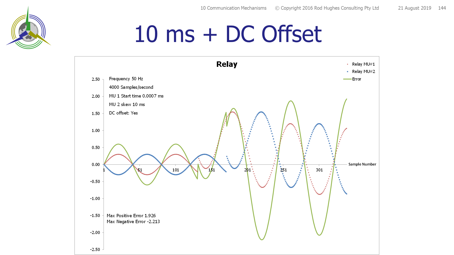
This shows that COHERENCY of time synchronisation of the Merging Units is critical, even if they don't have the same actual time, they just need to start their respective 1-second windows at the same instant, or at worst, within one microsecond of each other.
In theory you could use IRIG-B (U.S. military's Inter-Range Instrumentation Group, time code B) or 1-Pulse-Per-Second (1PPS) usually over coax.
IEC 61850‑9‑2LE recommended 1PPS over fibre rather than NTP or SNTP,
Even so most MU suppliers only provided IRIG-B over coaxial cable at least initially as that is how most relays were being time synchronised for Sequence OF Events.
IRIG-B/1PPS will only give you at best 0.1 millisecond coherency … but in a small network with only a few switches and low bandwidth utilisation, you might be lucky.
The “proper” synch method for Sampled Values is IEEE 1588 (2008) PTP v2 distributed over the same LAN as the SV, GOOSE and MMS.
However you must have a Master or Boundary Clock, and all the switches must support Transparent clock configuration and the IEDs of course must support operating as IEEE 1588 slave clocks.
Note within the one substation, it doesn't matte of the Master clock is showing precise actual time, ... just that all devices within the sub are synchronised to start their one second window at precisely the same instant within one microsecond of each other.
If you have substations at different locations relying on time synchronisation, you would then need GPS at both to synchronise the master Clock in each (technically the two clocks in each sub would now be called Boundary clocks as the GPS signal is the Master clock.
IEEE 1588 has a number of implementation profiles.
There is a specific implementation for IEC 61850 based systems described in IEC 61850-9-3, first published in 2016.
Protection Operation Forensics Based On Time
Anyone who has tried to provide forensic analysis of this knows that the more information recorded about what happened and when (with respect to each other), the better.
A common problem for many asset owners seeking to know why their circuit breaker tripped is the lack or somewhat limited Sequence Of Events records and/or waveform capture.
My saying is:
You have no right to expect to get something if you do not remember to specify that you MUST have it.
The typical contractor excuse of not recording all signals is that individual wire‑based systems would require a 10‑fold or more increase in the number of wires and associated terminations to draw, install, and commission as well as an I/O count limitation on the relays and recording units in the first place. That equals $$$$ which may make them uncompetitive and/or the asset owners budget just doesn't stretch that far in consideration that such records will hopefully only be needed "once in a blue moon"!!
Enter the virtual world of IEC 61850.
No physical issues limiting recording all signals as traffic flow .. well, apart from having a suitable traffic recording unit with appropriate triggers and storage size.. 👍👌
But first – what is the meaning of time (stamps) of GOOSE.
Actually, the normal Ethernet message time stamp included in all frames is meaningless. The Ethernet GOOSE frame has a time stamp <<T>> of when it was sent. But GOOSE has the heartbeat and fast repetition so for any one change of status, there will be a continuous stream of repeat messages with that same status all with different <<T>>.
The only REAL time as far as the various functions in the system is concerned is the time the first change of state message is RECEIVED by the subscribing IED. That message may not be the first of the repeat messages series if there has been for example an RSTP reconvergence.
GOOSE is intended to be FAST so message frames were stripped down to bare minimum Ethernet length. Usually they contain several status elements as 1 or 2 bits each as Pxxx.op.stVal plus their associated 8 bits quality flag Pxxx.Op.q. So in principle there is no problem to have say “100” elements representing all stages of protection function operations.
e.g. a 4‑stage overcurrent and 4‑stage earth fault has at least eight PTOC.Op.stVal and eight PTOC.Op.q values in its dataset representing when the relay operated. Add however many more Pxxx Logical Nodes are in the IED.
However equally the ONLY element that may be needed in the dataset is the "grouped" signal PTRC.Op.stVal and PTRC.Op.q in order to keep the "trip" GOOSE as FAST AS POSSIBLE with the smallest possible dataset and hence bandwidth requirement on the LAN.
But of course protection functions and their forensics often need to know what something simply STARTED to operate – it was above threshold and started timing out, but not yet resulting in a Pxxx.Op.stVal change of state. We need to know the value of Pxxx.Str.stVal changed state. So our 4-stage OC and 4-stage EF functions now have 16 status elements alone.
And not to forget that the protection forensics may also need to know when the quality flag Pxxx.Op.q (which has 12 bits itself) of the protection function changed state.
- Pxxx1.Op.stVal 1 bit
- Pxxx1.Op.q 12 bits
- Pxxx1.Str.stVal 1 bits
- Pxxx1.Str.q 12 bit
26 bits per Pxxx Logical Node. Hence just for 4-stage OC and 4-stage EF requires 204 bits in the dataset t be sent on the wire. If there was 100 Pxxx elements to be transmitted, it would be 2600 bits in the dataset plus of course the ethernet frame header and footer.
You might say "So what? - the LAN is at least 100 Mb/s, perhaps 1 Gb/s on the backbone"
True.
GOOSE bandwidth even after a change of state is minimal - it does not "flood" the network as analysed here: GOOSE "Flooding".
A fast retransmission with a one millisecond initial retransmit results in just 10 messages in that first second after the event so the 100 Pxxx elements from one IED only requires 26 kb/s bandwidth for the dataset payload of the frame.
OK, there may be even a dozen or so IEDs all "rattling through" a series of fast retransmit sequences at the same time, but still, at 1 Gb/s on the backbone or even a subscriber capable of only 100 Mb/s is hardly going to be bothered by the message rate or size.
Of course if you still had some concern about that, VLANs and/or Multicast Filters can assist as discussed here: /wiki/spaces/AP/pages/1487896577
But still that information does not tell us WHEN any <<stVal>> changed state in the publisher IED.
The subscribing IEDs (including any traffic recording device as Sequence of Events /waveform capture) only know when they RECEIVE a message with the first changed value.
It is almost possible to deduce when the first change of state message was sent by the publishing IED based on the subscribing IEDs analysis of the SeqNum of each message and the Ethernet frame time stamp <<T>> if you know what the initial setting of the fast repetition <<timeAllowedToLive>> value is for each publisher IED’s messages. A “simple” algorithm could then tell you what time the Ethernet message <<T>> was for the first change of state message.
But STILL that is not the EXACT time the Pxxx.Op.stVal changed value! It is only the time the message was created to be published on the LAN which takes some processing time inside the IED after the change of state actually occurred. To understand the difference, the maximum GOOSE latency of three milliseconds is from the time of change of state of the function, not from when it appeared on the LAN.
If we want the exact time that a function Pxxx.Op.stVal changed state we need to know its change of state time
Consider the time stamp to the millisecond of the time a LN status changed is 64 bits ...
- times two for two Data Attributes <<.Op>> and <<.Str>>
- plus the 26 bits of <<.Op>> and <<.Str>>
- gives 154 bits per Logical Node
- times "100" Pxxx LNs in the one IED is 15400 bits, plus header and footer, to be sent PER MESSAGE ... that is a LOT of bits on the LAN!!
- times 10 messages in the first second after an event status change is 154000 bits per second = 154kb/s
One could argue that is still relatively insignificant in terms of overall bandwidth of even a 100 Mb/s port speed.
However 1 second is "several life times" as far as protection time sequences are concerned where the circuit breaker probably needs to trip in well under 100 milliseconds.
So whilst port speed si important, message latency and delays is super-important!
The 15400 bits of data set alone through a 100 Mb's port takes 0.154 seconds to transmit out the port .. and that is repeated on the ingress port to the first switch and the last egress port to the destination IED as well as every switch-to-switch port pairs in between albeit at faster speed of say 1 Gb/s switch-to-switch, and then repeated on the ingress.
Given the fastest GOOSE needs a function-to-function latency of 3 milliseconds, the size of each message as it passes through a port becomes of concern - after all, that is why GOOSE and SV use "stripped down" Ethernet frames without the Layer 3 IP Address fields - the Ethernet Standard itself was specifically modified in the mid 1990's to provide for GOOSE and SV Ethernet frame types!.
We must also remember the queuing nature of switches themselves .. one they start sending a message, it has to wait till that has cleared the buffer before another message can be selected to be sent. So if a normal heartbeat message containing 100's of time stamps is in "mid-transmit" and another message arrives representing a change of state of a function in another IED, the import Pxxx.Op.stVal is going to be held up till teh longer message has all been sent.
So if we are concerned about the shortest possible length GOOSE message, why would we want to add in a LOT of time stamp overhead that the receiving IEDs will not use anyway?
Clearly sending every Pxxx.Op.t in every "trip Goose" is counter productive to the intent of GOOSE as a FAST transmittal of signals.
In any case the subscribing IED doesn't care what that value of time was. It only cares when it received the first message with a changed value of Pxxx.Op.stVal
So we have a conundrum - we want to send GOOSE as fast as possible, but we also want to record the time stamp of every change of Pxxx.Op.stVal, Pxxx.Op.q, Pxxx.Str.stVal, Pxxx.Str.q
We could rely on IEC 61850-8-1 MMS Reporting to send a complete message with all the necessary information from the source SERVER IED and somehow an MMS CLIENT IED device could process that to derive the Sequence of Events.
However given that GOOSE is such a small bandwidth, we could structure two GOOSE messages:
- one with a high priority tag and a 1 ms initial fast retransmit with just the "essential trip information"
- another with a lower priority tag with say a 10 ms initial fast retransmit including ALL the <<.t>> time stamps
| Note |
|---|
I hope that gives you some food for thought about time … Please consider my Contribution to CIGRE 2018 regarding time synchronisation security as RH41D and RH41P My Papers and Contributions |
| Column | ||||||||||||||
|---|---|---|---|---|---|---|---|---|---|---|---|---|---|---|
| ||||||||||||||
Copy this direct permanent link to this page: https://rhconsult.tiny.us/38wuakck
|
...