Selection and performance of Current Transformers are critical to protection system performance. Click to enlarge 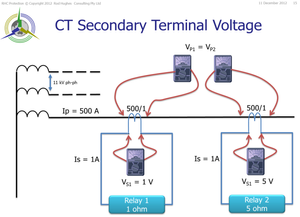
Physically a CT is made up of an iron core and windings
Physically a VT is made up of an iron core and windings
So emf and all sorts of Laws must apply equally to both - there is not special iron and no special copper being used in either CT or VT. But the first LAW we learn in electrical engineering is Ohm's Law V=I x R
Electricity flow anywhere MUST adhere to this Law. Two identical CTs with the identical current flowing through their primary windings is a great use case which brings usback to the absolute fundamental principle of electricity as Ohm's Law. We have a CT primary current flow through the CT primary winding resistance.
By Ohm’s Law the voltage that this current develops in flowing through that primary winding impedance is V=I.R
Since the bus bar or cable passing through the CT is exactly the same for both CTs, they have the same R
So the same R and the same I means the same Vp on both CTs.
No escaping that. Since the primary current is rated 500 A, and the CT is designed that it won’t saturate until at least 20 x rated current, both CTs will produce rated secondary current of 1 A.
No escaping that. The left-hand CT will push its 1 A output through the 1 ohm burden.
Therefore it will have the voltage generated BY THE BURDEN at its terminals as Vs1 = I x R = 1V.
No escaping that. The right-hand CT will push its 1 A output through the 5 ohm burden.
The voltage at its terminals is also develop BY THE BURDEN as Vs2 = 1 x 5 = 5V
No escaping that. There is nothing “magical” or any other Law for either CT that could obviate Ohm’s Law applying in these conditions. The outcome is that one CT has a voltage transformation of Vp/1 V whilst the other identical CT has a voltage transformation ratio of Vp/5 V
Vp/Ns1 is not equal to Vp/Ns2 even though the CT is physically identical and the primary current is identical.
Still can’t get away from that!
The Volts/Turn Law appears to have been broken! But has it? The Volts/Turn primary must equal the Volts\/Turn secondary.
But the Volts/Turn in this equation is NOT referring to the secondary TERMINAL VOLTAGE as it would for a VT..
It is referring to the internal voltage which is developed according to the formula E = 4.44fNaB formula. (Click to enlarge) 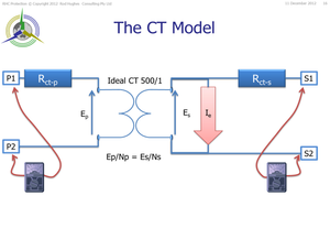
(Note the old Australian Standard AS 1675 used to specify its P class CT as the CT terminal voltage i.e. a 10P150 F20 meant the CT will perform correctly up to 20 times rated current with 10% accuracy and will be able to generate Vs = 150V at its terminals at 20 x rated current – i.e. the max burden is 7.5 ohms. Personally I prefer this than the new standards aligned to IEC) |