A common requirement in transformer installation is to ensure the correct winding connections for a Delta-Star transformer Start with the star side since both ph-ph and ph-n vectors exist we already know that the "s2" terminals are all connected as the common star point. 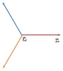 Image Added Image Added
Assume A ph-n is at 0 degrees We can now see which we will show as horizontal to the right We therefore have 3 star voltages 120 degree apart We know that there is a winding associated with each phase. Each of the phase The angle of that voltage is at 0 degrees \hence the angle f the voltage eon its other winding is also at zero degrees. We therefore have 3 star voltages 120 degree apart And 3 voltages on the other winding 120 degrees apart So taking these other windings we have the choice of connecting them in star or delta If in star then either the winding is connected to give 0 degree phase shift or 180 degree phase shift If in delta we can decide which end connects to which other end of which other phase i.e. taking the A winding, end 1 can connect to either B winding end 2 or C winding end 2star windings is located on one of the limbs of the transformer core (red windings below) - that same limb has another winding (blue windings) which we wish to connect in Delta. The question is what end of each of the delta windings is connected to which other windings of the delta and which end? 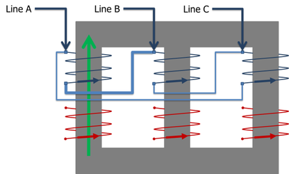 Image Added Image Added
or are the windings connected this way: 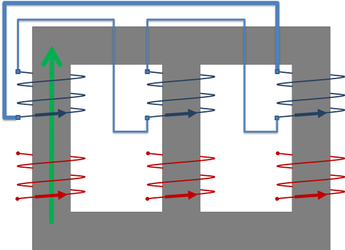 Image Added Image Added
We can see from the diagram that the flux through each limb passes through both windings, therefore the voltage on each winding must be in phase. Clearly the star winding has the phase-to-neutral voltage appearing across s1 to s2.
That flux must therefore create a corresponding voltage in the delta windings - noting that delta windings have the phaseto-phase voltage appearing across the winding. Therefore the polarity of the voltage on the corresponding winding P1 to P2 must be in phase with the voltage appearing on s1 to s2 So starting with the "a" phase we get a delta winding vector relationship P1 to P2 in phase with the a phase star winding. 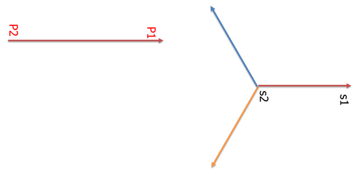 Image Added Image Added
Similarly we can draw the rest of the delta winding voltage vectors. 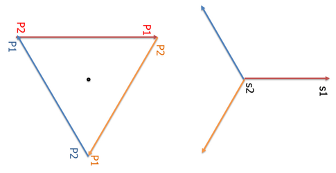 Image Added Image Added
We can now see we have a connection diagram of which P1 connects to which P2 giving us this arrangement: 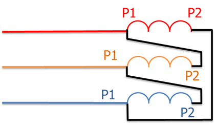 Image Added Image Added
The final question is whether this is Dyn1 or Dyn11? Although there is no actual neutral point in the delta winding, we can imagine a neutral point at the centre of the delta vectors. We can therefore imagine a phase-to-neutral vector as shown here with its "top end" meeting up with the "top end" of the red phase vector : 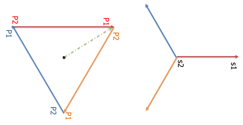 Image Added Image Added
So we can now see the phase relationship between the imaginary delta winding phase-to-neutral voltage with the actual phase-to-neutral voltage of the star winding. It is clear the star winding is rotated clockwise by 30 degrees with respect to the delta. So on a clock face, 30 degrees in a clockwise direction from the 12 o'clock position would be 1 o'clock Therefore this arrangement is Dyn1.
However we could equally have drawn the voltage vectors as this star arrangement but a different selection of the delta winding interconnections 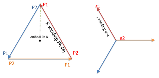 Image Added Image Added
We can now see that the star winding actual phase-to-neutral voltage is 30 degrees anticlockwise to the imaginary delta winding phase-to-neutral voltage. This is therefore a Dyn11 connection: 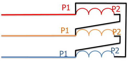 Image Added Image Added
|